Blind Flange
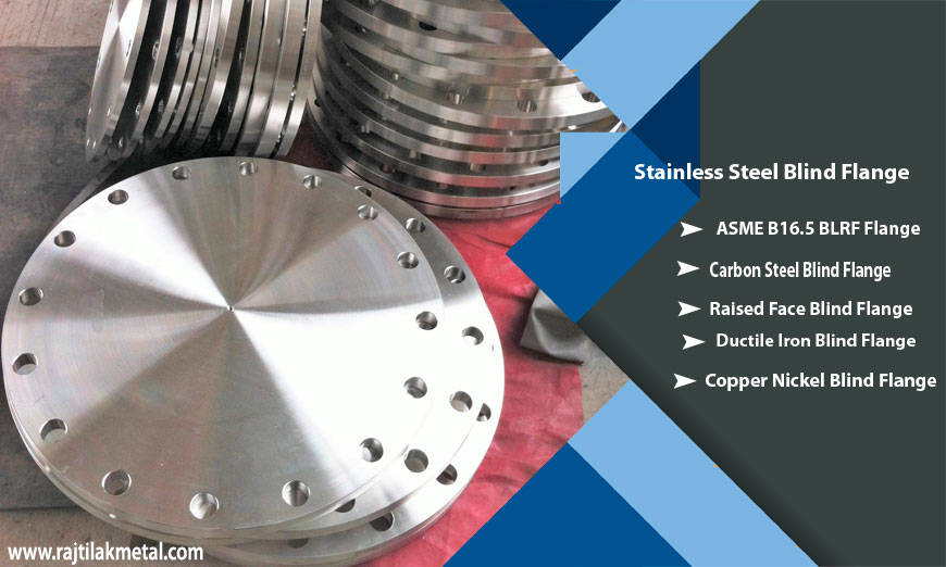
ASME B16.5 Stainless Steel Blind Flange Manufacturer In India, check ANSI B16.5 BLRF Flanges Dimensions In Class 150 To 2500# & Weight.
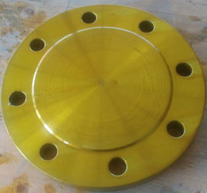
ASME B16.5 Blind Flange
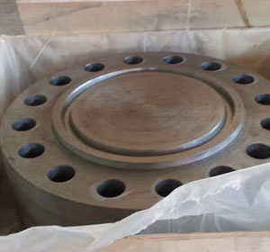
Stainless Steel Blind Flange
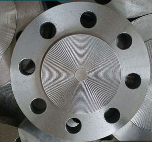
Carbon Steel Blind Flange
How Does A Blind Flange Work?
ASME B16.5 Blind Flange have diameters from ½ inches to 24 inches and they are made up of different materials. They are also made in different shapes according to the need. BLRF flange has a raised face which allows for much grip at installation and high tensile strength. Blind flange dimensions vary according to the specifications and types. Blind flange weight is important in considering for which application it is used for. the Blind flange weight chart can show the difference in weight for different material composition for bling flanges and raised face ones.
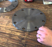
Mechanical Joint Blind Flange
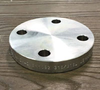
ANSI B16.5 BLRF Flange
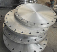
Aluminum Blind Flange
Table of contents
BLRF Class 150 To 2500 Dimensions
DIN BLRF Flange Dimensions
- BLRF Flange Weight
- ASME B16.5 Blind Flange Specification List
- Mechanical Joint Blind Flange Pressure Rating And Temperature Ratings
- ANSI B6.5 Blind Flange Tolerances
- Blind Flange Thickness Calculation For Pressure Vessel
- Blind Flange Bolt Pattern And Size
- Standard Blind Flange Sizes Chart
- Popular Types Of ASME B16.5 Blind Flange
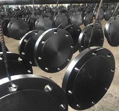
What Is The Difference Between Blank Flange And Blind Flange?
A comprehensive Blank flange will provide an idea of the dimensions and sizes. ANSI Blank flange sizes for B16.5 specification range up to NPS 24. The thickness of the wall in the class 150 Blank flange dimensions would be lower than the thickness of a class 150 flange due to the additional pressure it is excerpted onto.
The classes are a way of blind flange that allows customers to order the correct class for the appropriate need. Stainless Steel Blind Flange can be different with different specification methods as well. The PN series is a way of specifying the pressure class in bars and the properties such as the hole size and bolt circle diameter. For example the pn16 blind flange dimensions would align with the PN number which is 16.
BLRF Flange Use In Hydraulic Applications?
BLRF Flange are applied in different industries and applications. One of the common application for the stainless steel blind flange is to cover the opening at the end of a system. Usually, test systems in chemical, marine and hydraulic applications have such open end pipes where blind flanges could be used.
Blind Flange Drawing
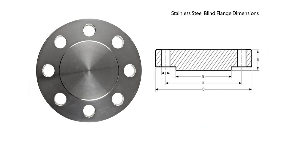
Class 150 Blind Flange Dimensions
| NPS (Normal Pipe Sizes) | "A" (O.D.) Outside Daimeter |
"B" (Thickness) |
"C" (RF Daimeter) |
"D" (B.C.D.) |
# Bolt Holes |
Daimeter of Bolt Holes |
Approx. Weight In Kg |
|---|---|---|---|---|---|---|---|
| 1/2" | 3-1/2 | 7/16 | 1-3/8 | 2-3/8 | 4 | 5/8 | 2 |
| 3/4" | 3-7/8 | 1/2 | 1-11/16 | 2-3/4 | 4 | 5/8 | 2 |
| 1" | 4-1/4 | 9/16 | 2 | 3-1/8 | 4 | 5/8 | 2 |
| 1-1/4" | 4-5/8 | 5/8 | 2-1/2 | 3-1/2 | 4 | 5/8 | 3 |
| 1-1/2" | 5 | 11/16 | 2-7/8 | 3-7/8 | 4 | 5/8 | 3 |
| 2" | 6 | 3/4 | 3-5/8 | 4-3/4 | 4 | 3/4 | 4 |
| 2-1/2" | 7 | 7/8 | 4-1/8 | 5-1/2 | 4 | 3/4 | 7 |
| 3" | 7-1/2 | 15/16 | 5 | 6 | 4 | 3/4 | 9 |
| 3-1/2" | 8-1/2 | 15/16 | 5-1/2 | 7 | 8 | 3/4 | 13 |
| 4" | 9 | 15/16 | 6-3/16 | 7-1/2 | 8 | 3/4 | 17 |
| 5" | 10 | 15/16 | 7-5/16 | 8-1/2 | 8 | 7/8 | 20 |
| 6" | 11 | 1 | 8-1/2 | 9-1/2 | 8 | 7/8 | 27 |
| 8" | 13-1/2 | 1-1/8 | 10-5/8 | 11-3/4 | 8 | 7/8 | 47 |
| 10" | 16 | 1-3/16 | 12-3/4 | 14-1/4 | 12 | 1 | 67 |
| 12" | 19 | 1-1/4 | 15 | 17 | 12 | 1 | 123 |
| 14" | 21 | 1-3/8 | 16-1/4 | 18-3/4 | 12 | 1-1/8 | 139 |
| 16" | 23-1/2 | 1-7/16 | 18-1/2 | 21-1/4 | 16 | 1-1/8 | 187 |
| 18" | 25 | 1-9/16 | 21 | 22-3/4 | 16 | 1-1/4 | 217 |
| 20" | 27-1/2 | 1-11/16 | 23 | 25 | 20 | 1-1/4 | 283 |
| 24" | 32 | 1-7/8 | 27-1/4 | 29-1/2 | 20 | 1-3/8 | 415 |
Class 300 Blind Flange Dimensions
| NPS (Normal Pipe Size) | "A" (O.D.) Ouside Daimeter |
"B" (Thickness) |
"C" (RF Daimeter) |
"D" (B.C.D.) |
# Bolt Holes |
Daimeter of Bolt Holes |
Approx. Weight in Kilogram |
|---|---|---|---|---|---|---|---|
| 1/2" | 3-3/4 | 9/16 | 1-3/8 | 2-5/8 | 4 | 5/8 | 2 |
| 3/4" | 4-5/8 | 5/8 | 1-11/16 | 3-1/4 | 4 | 3/4 | 3 |
| 1" | 4-7/8 | 11/16 | 2 | 3-1/2 | 4 | 3/4 | 4 |
| 1-1/4" | 5-1/4 | 3/4 | 2-1/2 | 3-7/8 | 4 | 3/4 | 6 |
| 1-1/2" | 6-1/8 | 13/16 | 2-7/8 | 4-1/2 | 4 | 7/8 | 7 |
| 2" | 6-1/2 | 7/8 | 3-5/8 | 5 | 8 | 3/4 | 8 |
| 2-1/2" | 7-1/2 | 1 | 4-1/8 | 5-7/8 | 8 | 7/8 | 12 |
| 3" | 8-1/4 | 1-1/8 | 5 | 6-5/8 | 8 | 7/8 | 16 |
| 3-1/2" | 9 | 1-3/16 | 5-1/2 | 7-1/4 | 8 | 7/8 | 21 |
| 4" | 10 | 1-1/4 | 6-3/16 | 7-7/8 | 8 | 7/8 | 28 |
| 5" | 11 | 1-3/8 | 7-5/16 | 9-1/4 | 8 | 7/8 | 37 |
| 6" | 12-1/2 | 1-7/16 | 8-1/2 | 10-5/8 | 12 | 7/8 | 48 |
| 8" | 15 | 1-5/8 | 10-5/8 | 13 | 12 | 1 | 79 |
| 10" | 17-1/2 | 1-7/8 | 12-3/4 | 15-1/4 | 16 | 1-1/8 | 122 |
| 12" | 20-1/2 | 2 | 15 | 17-3/4 | 16 | 1-1/4 | 183 |
| 14" | 23 | 2-1/8 | 16-1/4 | 20-1/4 | 20 | 1-1/4 | 241 |
| 16" | 25-1/2 | 2-1/4 | 18-1/2 | 22-1/2 | 20 | 1-3/8 | 315 |
| 18" | 28 | 2-3/8 | 21 | 24-3/4 | 24 | 1-3/8 | 414 |
| 20" | 30-1/2 | 2-1/2 | 23 | 27 | 24 | 1-3/8 | 515 |
| 24" | 36 | 2-3/4 | 27-1/4 | 32 | 24 | 1-5/8 | 800 |
Class 400 Blind Flange Dimensions
| NPS (Normal Pipe Sizes) | Outside Daimeter | Circle Of Bolt (BC) | Raised Face (R) | Raised Face (RF) | Thickness Of Raised Face (T) | Thickness Of Flat Face (T2) | Hole Of Bolt (B) | Number of Bolt Holes | ||||||
|---|---|---|---|---|---|---|---|---|---|---|---|---|---|---|
| 1/2" | 3.75" | 2.62" | 0.12" | .250" | 0.81" | 0.56" | 0.62" | 4 | ||||||
| 3/4" | 4.62" | 3.25" | 0.12" | .250" | 0.87" | 0.62" | 0.75" | 4 | ||||||
| 1" | 4.88" | 3.50" | 0.12" | .250" | 0.94" | 0.69" | 0.75" | 4 | ||||||
| 1-1/4" | 5.25" | 3.88" | 0.19" | .250" | 1.06" | 0.81" | 0.75" | 4 | ||||||
| 1-1/2" | 6.12" | 4.50" | 0.25" | .250" | 1.13" | 0.88" | 0.88" | 4 | ||||||
| 2" | 6.50" | 5.00" | 0.31" | .250" | 1.25" | 1.00" | 0.75" | 8 | ||||||
| 2-1/2" | 7.50" | 5.88" | 0.31" | .250" | 1.37" | 1.12" | 0.88" | 8 | ||||||
| 3" | 8.25" | 6.62" | 0.38" | .250" | 1.50" | 1.25" | 0.88" | 8 | ||||||
| 3-1/2" | 9.00" | 7.25" | 0.38" | .250" | 1.63" | 1.38" | 1.00" | 8 | ||||||
| 4" | 10.00" | 7.88" | 0.44" | .250" | 1.63" | 1.38" | 1.00" | 8 | ||||||
| 5" | 11.00" | 9.25" | 0.44" | .250" | 1.75" | 1.50" | 1.00" | 8 | ||||||
| 6" | 12.50" | 10.62" | 0.50" | .250" | 1.87" | 1.62" | 1.00" | 12 | ||||||
| 8" | 15.00" | 13.00" | 0.50" | .250" | 2.13" | 1.88" | 1.12" | 12 | ||||||
| 10" | 17.50" | 15.25" | 0.50" | .250" | 2.37" | 2.12" | 1.25" | 16 | ||||||
| 12" | 20.50" | 17.75" | 0.50" | .250" | 2.50" | 2.25" | 1.38" | 16 | ||||||
| 14" | 23.00" | 20.25" | 0.50" | .250" | 2.63" | 2.38" | 1.38" | 20 | ||||||
| 16" | 25.50" | 22.50" | 0.50" | .250" | 2.75" | 2.50" | 1.50" | 20 | ||||||
| 18" | 28.00" | 24.75" | 0.50" | .250" | 2.87" | 2.62" | 1.50" | 24 | ||||||
| 20" | 30.50" | 27.00" | 0.50" | .250" | 3.00" | 2.75" | 1.62" | 24 | ||||||
| 22" | 33.00" | 29.25" | 0.50" | .250" | 3.13" | 2.88" | 1.75" | 24 | ||||||
| 24" | 36.00" | 32.00" | 0.50" | .250" | 3.25" | 3.00" | 1.88" | 24 |
Class 600 Blind Flange Dimensions
| ø | D | b | g | k | Holes | l | Kg. |
|---|---|---|---|---|---|---|---|
| 1/2" | 95,2 | 14,3 | 34,9 | 66,7 | 4 | 15,9 | 0,700 |
| 3/4" | 117,5 | 15,9 | 42,9 | 82,5 | 4 | 19,0 | 1,200 |
| 1" | 123,8 | 17,5 | 50,8 | 88,9 | 4 | 19,0 | 1,500 |
| 1 1/4" | 133,3 | 20,6 | 63,5 | 98,4 | 4 | 19,0 | 2,000 |
| 1 1/2" | 155,6 | 22,2 | 73,0 | 114,3 | 4 | 22,2 | 3,200 |
| 2" | 165,1 | 25,4 | 92,1 | 127,0 | 8 | 19,0 | 4,300 |
| 2 1/2" | 190,5 | 28,6 | 104,8 | 149,2 | 8 | 22,2 | 6,000 |
| 3" | 209,5 | 31,7 | 127,0 | 168,3 | 8 | 22,2 | 8,000 |
| 3 1/2" | 228,6 | 34,9 | 139,7 | 184,1 | 8 | 25,4 | 10,500 |
| 4" | 273,0 | 38,1 | 157,2 | 215,9 | 8 | 25,4 | 18,000 |
| 5" | 330,2 | 44,4 | 185,7 | 266,7 | 8 | 28,6 | 28,500 |
| 6" | 355,6 | 47,6 | 215,9 | 292,1 | 12 | 28,6 | 35,500 |
| 8" | 419,1 | 55,6 | 269,9 | 349,2 | 12 | 31,7 | 58,000 |
| 10" | 508,0 | 63,5 | 323,8 | 431,8 | 16 | 34,9 | 98,000 |
| 12" | 558,8 | 66,7 | 381,0 | 488,9 | 20 | 34,9 | 125,000 |
| 14" | 603,2 | 69,8 | 412,7 | 527,0 | 20 | 38,1 | 151,000 |
| 16" | 685,8 | 76,2 | 469,9 | 603,2 | 20 | 41,3 | 215,000 |
| 18" | 742,9 | 82,5 | 533,4 | 654,0 | 20 | 44,4 | 287,000 |
| 20" | 812,8 | 88,9 | 584,2 | 723,9 | 24 | 44,4 | 366,000 |
| 22" | 869,9 | 95,2 | 641,2 | 777,9 | 24 | 47,6 | 437,000 |
| 24" | 939,8 | 101,6 | 692,1 | 838,2 | 24 | 50,8 | 532,000 |
Class 900 Blind Flange Dimensions
| NPS (Normal Pipe Size) | O.D. (Outside Daimeter) | Circle Of Bolt (BC) | Raised Face (R) | Raised Face (RF) | Thickness Of Raised Face (T) | Thickness Of Flat Face (T2) | Hole Of Bolt (B) | Number of Bolt Holes |
|---|---|---|---|---|---|---|---|---|
| 3" | 9.50" | 7.50" | 5.00" | .250" | 1.75" | 1.50" | 1.00" | 8 |
| 4" | 11.50" | 9.25" | 6.19" | .250" | 2.00" | 1.75" | 1.25" | 8 |
| 5" | 13.75" | 11.00" | 7.31" | .250" | 3.25" | 3.00" | 1.38" | 8 |
| 6" | 15.00" | 12.50" | 8.50" | .250" | 2.44" | 2.19" | 1.25" | 12 |
| 8" | 18.50" | 15.50" | 10.63" | .250" | 2.75" | 2.50" | 1.50" | 12 |
| 10" | 21.50" | 18.50" | 12.75" | .250" | 3.00" | 2.75" | 1.50" | 16 |
| 12" | 24.00" | 21.00" | 15.00" | .250" | 3.38" | 3.13" | 1.50" | 20 |
| 14" | 25.25" | 22.00" | 16.25" | .250" | 3.63" | 3.38" | 1.63" | 20 |
| 16" | 27.75" | 24.25" | 18.50" | .250" | 3.75" | 3.50" | 1.75" | 20 |
| 18" | 31.00" | 27.00" | 21.00" | .250" | 4.25" | 4.00" | 2.00" | 20 |
| 20" | 33.75" | 29.50" | 23.00" | .250" | 4.50" | 4.25" | 2.13" | 20 |
| 24" | 41.00" | 35.50" | 27.25" | .250" | 5.75" | 5.50" | 2.63" | 20 |
Class 1500 Blind Flange Dimensions
| NPS | Outside Daimeter Flange | Thickness Of Flange Minimum | Daimeter of Hub | Daimeter of Bolt Circle | Daimeter of Bolt Holes | Number of Bolts | Daimeter of Bolts(inches) | Approx. Weight in kilogram | ||
|---|---|---|---|---|---|---|---|---|---|---|
| inches | dn | O | C | X | BC | BH | BN | BD | KG/PCS | LB/PCS |
| 1/2 | 15 | 120.7 | 22.4 | 38.1 | 82.6 | 22.4 | 4 | 3/4 | 1.9 | 4.2 |
| 3/4 | 20 | 130 | 25.4 | 44.5 | 88.9 | 22.4 | 4 | 3/4 | 2.7 | 6 |
| 1 | 25 | 149.4 | 28.4 | 52.3 | 101.6 | 25.4 | 4 | 7/8 | 3.7 | 8.1 |
| 1-1/4 | 32 | 158.8 | 28.4 | 63.5 | 111.3 | 25.4 | 4 | 7/8 | 4.3 | 9.5 |
| 1-1/2 | 40 | 177.8 | 31.8 | 69.9 | 124 | 28.4 | 4 | 1 | 5.9 | 13 |
| 2 | 50 | 215.9 | 38.1 | 104.6 | 165.1 | 25.4 | 8 | 7/8 | 11.3 | 24.9 |
| 2-1/2 | 65 | 244.3 | 41.1 | 124 | 190.5 | 28.4 | 8 | 1 | 16 | 35.2 |
| 3 | 80 | 266.7 | 47.8 | 133.4 | 190.5 | 25.4 | 8 | 7/8 | 19.5 | 43 |
| 4 | 100 | 311.2 | 53.8 | 162.1 | 235 | 31.8 | 8 | 1 1/8 | 33 | 72.8 |
| 5 | 125 | 374.7 | 73.2 | 196.9 | 279.4 | 35.1 | 8 | 1 1/4 | 60 | 132 |
| 6 | 150 | 393.7 | 82.6 | 228.6 | 317.5 | 31.8 | 12 | 1 1/8 | 75 | 165 |
| 8 | 200 | 482.6 | 91.9 | 292.1 | 393.7 | 38.1 | 12 | 1 3/8 | 125 | 275 |
| 10 | 250 | 584.2 | 108 | 368.3 | 469.9 | 38.1 | 16 | 1 3/8 | 215 | 474 |
| 12 | 300 | 673.1 | 124 | 450.9 | 533.4 | 38.1 | 20 | 1 3/8 | 316 | 697 |
| 14 | 350 | 749.3 | 133.4 | 495.3 | 558.8 | 41.1 | 20 | 1 1/2 | ||
| 16 | 400 | 825.5 | 146.1 | 552.5 | 616 | 44.5 | 20 | 1 5/8 | ||
| 18 | 450 | 914.4 | 162.1 | 596.9 | 685.8 | 50.8 | 20 | 1 7/8 | ||
| 20 | 500 | 984.3 | 177.8 | 641.4 | 749.3 | 53.8 | 20 | 2 | ||
| 24 | 600 | 1168.4 | 203.2 | 762 | 901.7 | 66.5 | 20 | 2 1/2 | ||
Class 2500 Blind Flange Dimensions
| NPS | Outside Daimeter Of Flange | Thickness Of Flange Minimum | Daimeter of Bolt Circle | Daimeter of Bolt Holes | Number of Bolts | Daimeter of Bolts (inches) | KG | LB | |
|---|---|---|---|---|---|---|---|---|---|
| inch | dn | O | C | BC | BH | BN | BD | ||
| 1/2 | 15 | 133.4 | 30.2 | 88.9 | 22.4 | 4 | 3/4 | 3 | 7 |
| 3/4 | 20 | 139.7 | 31.8 | 95.3 | 22.4 | 4 | 3/4 | 4.5 | 10 |
| 1 | 25 | 158.8 | 35.1 | 108 | 25.4 | 4 | 7/8 | 5 | 12 |
| 1-1/4 | 32 | 184.2 | 38.1 | 130 | 28.4 | 4 | 1 | 8 | 18 |
| 1-1/2 | 40 | 203.2 | 44.5 | 146.1 | 31.8 | 4 | 1 1/8 | 11 | 25 |
| 2 | 50 | 235 | 50.8 | 171.5 | 28.4 | 8 | 1 | 17 | 38 |
| 2-1/2 | 65 | 266.7 | 57.2 | 196.9 | 31.8 | 8 | 1 1/8 | 25 | 55 |
| 3 | 80 | 304.8 | 66.5 | 228.6 | 35.1 | 8 | 1 1/4 | 39 | 86 |
| 4 | 100 | 355.6 | 76.2 | 273.1 | 41.1 | 8 | 1 1/2 | 60 | 133 |
| 5 | 125 | 419.1 | 91.9 | 323.9 | 47.8 | 8 | 1 3/4 | 101 | 223 |
| 6 | 150 | 482.6 | 108 | 368.3 | 53.8 | 8 | 2 | 156 | 345 |
| 8 | 200 | 552.5 | 127 | 438.2 | 53.8 | 12 | 2 | 242 | 533 |
| 10 | 250 | 673.1 | 165.1 | 539.8 | 66.5 | 12 | 2 1/2 | 465 | 1023 |
| 12 | 300 | 762 | 184.2 | 619.3 | 73.2 | 12 | 2 3/4 | 665 | 1463 |
Check Carbon Steel Blind Flange Price List, Specification List Of BLRF Flanges As Per ASME B16.5.
BLRF Flange Weight
| Nominal Pipe Sizes (NPS) | Slip On (SORF) | Threaded (NPT) | Socket Weld (SWRF) | Lap Joint (Loose) | Blind (BLRF) | Weld Neck (WRNR) |
|---|---|---|---|---|---|---|
| ½ | 1 | 1 | 2 | 1 | 2 | 2 |
| ¾ | 2 | 2 | 2 | 2 | 2 | 2 |
| 1 | 2 | 2 | 2 | 2 | 2 | 3 |
| 1¼ | 3 | 3 | 3 | 3 | 3 | 3 |
| 1½ | 3 | 3 | 3 | 3 | 4 | 4 |
| 2 | 5 | 5 | 5 | 5 | 5 | 6 |
| 2½ | 8 | 8 | 8 | 8 | 7 | 10 |
| 3 | 9 | 9 | 9 | 9 | 9 | 11.5 |
| 3½ | 11 | 12 | 11 | 11 | 13 | 12 |
| 4 | 13 | 13 | 13 | 13 | 17 | 16.5 |
| 5 | 15 | 15 | 15 | 15 | 20 | 21 |
| 6 | 19 | 19 | 19 | 19 | 27 | 26 |
| 8 | 30 | 30 | 30 | 30 | 47 | 42 |
| 10 | 43 | 43 | 43 | 43 | 70 | 54 |
| 12 | 64 | 64 | 64 | 64 | 123 | 88 |
| 14 | 90 | 90 | 90 | 105 | 140 | 114 |
| 16 | 106 | 98 | 98 | 140 | 180 | 140 |
| 18 | 130 | 130 | 130 | 160 | 220 | 165 |
| 20 | 165 | 165 | 165 | 195 | 285 | 197 |
| 22 | 185 | 185 | 185 | 245 | 355 | 225 |
| 24 | 220 | 220 | 220 | 275 | 430 | 268 |
Blind flange price list in India is very competitive. It varies from supplier to supplier. The qualities differ as well. ASME B16.5 blind flange dimensions constitute to the price too. The smaller the size, the lower the weight and lower the price. Dimensions of the
Maximum Pressure Of Mechanical Joint Blind Flange And One Stop Shop For All Copper/ Grooved/ Aluminum/ Ductile Iron BLRF Flanges
ASME B16.5 Blind Flange Specification List
| Material Specification Of : | ASME B16.5 Blind Flange |
|---|---|
| Bolt Type | high strength bolts medium strength bolts low strength bolts |
| European Standard Flanges | JIS B2220 Flanges (5k to 30k) and KS1503 flanges |
| Russian-Standard Flanges | GOST 12820 / 12821-80, DIN, UNI, EN 1092-1 |
| South African Standard Flanges | SANSflanges And SABS flanges |
| Surface Finish | smooth, concentric serrated, stock |
| Gaskets Types | Full Face Gasket Flat Ring Gasket Metallic Ring Gakset |
| Standard Cover : | pressure ratings & temperature ratings, materials, marking, dimensions, weight, tolerances, testing |
| Contact Faces | RTJ (Ring Type Joint), FF (Flat Face), RF (Raised Face), T/G (Tongue And Groove ), M/F (Male And Female) |
| Size Chart | Normal Pipe Size 1/2 to NPS 24" |
| Materials | Stainless Steel (Grade 304/L, 316/L), Carbon Steel (ASTM A105 And ASTM A350), Alloy Steel (ASTM A182), Mild Steel, Duplex Steel, Pressure Vessel Steel, Titanium, Super Duplex Steel, Nickel Alloy, Monel, Inconel, Hastelloy, Copper Nickel, Cast Iron, Wrought Iron. |
| Thickness | Normal Pipe Size ≤ 18 |
| Bore Diameter | Normal Pipe ≤ 10 |
| Flanges Standards | EN 1092-1, JIS, ASME B16.5, ASME B16.47 type A, UNI, DIN |
| Pressure Rating | Class 150 To Class 2500 |
| High Temperature | Above 200°C (400°F) For Class 150 Or Above 400°C (750°F) |
| Low Temperature | Above -29 Degree C (−20°F) |
| Common Types Of Flanges: | Slip On (SORF), Weld Neck (WNRF), Blind (BLRF), Lap Joint (Loose), Threaded (NPT), Socket-Weld (SWRF) |
| Special Types Of Flanges : | Nipoflange, Elboflange, Latroflange, Swivel Flanges, Expanding Flanges, Reducing Flanges, Weldoflange |
| Marking Standard | Name of Manufacturer Schedule Type of Flange Facing Nominal Pipe Size Pressure Class ASME B16 Designation |
| Advantages Of Pipe Flange | Used to Connect Pipe System Easy Repair Pipe System Assembled Without Welding |
These ANSI CS Flanges BLRF are designed in accordance with the industrial standards and are fabricated using quality material. Ductile Iron Blind Flanges are known for excellent resistance against corrosion, excellent performance and durability. Santosh Pipe Fitting is reckoned amongst the prominent in ASME 16.5 ASME B16.5 Stainless Steel Blind Flanges Manufacturers and manufacturers of a wide range of industrial ASME B16.5 Blind Flanges.
Mechanical Joint Blind Flange Pressure Rating And Temperature Ratings
| ASME B16.5 Pressure Pressure | |||||||
|---|---|---|---|---|---|---|---|
| Temperature (°C) | Class | ||||||
| Class 150 | Class 300 | Class 400 | Class 600 | Class 900 | Class 1500 | Class 2500 | |
| -29 - 38 | 19.8 | 51.7 | 68.9 | 103.4 | 155 | 259 | 431 |
| 50 | 19.5 | 51.7 | 68.9 | 103.4 | 155 | 259 | 431 |
| 100 | 17.7 | 51.5 | 68.7 | 103.0 | 155 | 258 | 429 |
| 150 | 15.8 | 50.2 | 66.8 | 100.3 | 151 | 251 | 418 |
| 200 | 13.8 | 48.6 | 64.8 | 97.2 | 146 | 243 | 405 |
| 250 | 12.1 | 46.3 | 61.7 | 92.7 | 139 | 232 | 386 |
| 300 | 10.2 | 42.9 | 57.0 | 85.7 | 129 | 214 | 357 |
| 325 | 9.3 | 41.4 | 55.0 | 82.6 | 124 | 207 | 344 |
| 350 | 8.4 | 40.0 | 53.4 | 80.0 | 120 | 200 | 334 |
| 375 | 7.4 | 37.8 | 50.4 | 75.7 | 114 | 189 | 315 |
| 400 | 6.5 | 34.7 | 46.3 | 69.4 | 104 | 174 | 290 |
| 425 | 5.5 | 28.8 | 38.4 | 57.5 | 86.3 | 144 | 240 |
| 450 | 4.6 | 23.0 | 30.7 | 46.0 | 69.0 | 115 | 192 |
| 475 | 3.7 | 17.1 | 22.8 | 34.2 | 51.3 | 85.4 | 142 |
| 500 | 2.8 | 11.6 | 15.4 | 23.2 | 34.7 | 57.9 | 96.5 |
| 538 | 1.4 | 5.9 | 7.9 | 11.8 | 17.7 | 29.5 | 49.2 |
ANSI B6.5 Blind Flange Tolerances
| ASME B16.5 | Tolerance | |
|---|---|---|
| A | Outside Diameter (O.D.) |
|
| D | Inside Diameter |
|
| B | Diameter of contact face |
|
| J | Diameter of hub at base |
|
| H | Diameter of hub at point of welding |
|
| P | Drilling |
|
| Eccentricity of bolt circle with respect to facing |
|
|
| C | Thickness |
|
| K | Length of hub |
|
View Difference Between Blank Flange VS Blind Flanges, ASME B16.5 BLRF Flanges Tolerance Formula.
Blind Flange Thickness Calculation For Pressure Vessel
| ANSI B16.5 Flanges Wall Thickness | ||||||||||||||
|---|---|---|---|---|---|---|---|---|---|---|---|---|---|---|
| NPS (Normal Pipe Sizes) | Outside Daimeter (O.D.) | Schedule 10 | Schedule 20 | Schedule 30 | STD Wall | Schedule 40 | Schedule 60 | EXT Hvy | Schedule 80 | Schedule 100 | Schedule 120 | Schedule 140 | Schedule 160 | XX Hvy |
| ½ | 0.84 | 0.083 | ... | ... | 0.109 | 0.109 | ... | 0.147 | 0.147 | ... | ... | ... | 0.188 | 0.294 |
| ¾ | 1.05 | 0.083 | ... | ... | 0.113 | 0.113 | ... | 0.154 | 0.154 | ... | ... | ... | 0.219 | 0.308 |
| 1 | 1.315 | 0.109 | ... | ... | 0.133 | 0.133 | ... | 0.179 | 0.179 | ... | ... | ... | 0.25 | 0.358 |
| 1 ¼ | 1.66 | 0.109 | ... | ... | 0.14 | 0.14 | ... | 0.191 | 0.191 | ... | ... | ... | 0.25 | 0.382 |
| 1 ½ | 1.9 | 0.109 | ... | ... | 0.145 | 0.145 | ... | 0.2 | 0.2 | ... | ... | ... | 0.281 | 0.4 |
| 2 | 2.375 | 0.109 | ... | ... | 0.154 | 0.154 | ... | 0.218 | 0.218 | ... | ... | ... | 0.344 | 0.436 |
| 2 ½ | 2.875 | 0.12 | ... | ... | 0.203 | 0.203 | ... | 0.276 | 0.276 | ... | ... | ... | 0.375 | 0.552 |
| 3 | 3.5 | 0.12 | ... | ... | 0.216 | 0.216 | ... | 0.3 | 0.3 | ... | ... | ... | 0.438 | 0.6 |
| 3 ½ | 4 | 0.12 | ... | ... | 0.226 | 0.226 | ... | 0.318 | 0.318 | ... | ... | ... | ... | 0.636 |
| 4 | 4.5 | 0.12 | ... | ... | 0.237 | 0.237 | ... | 0.337 | 0.337 | ... | 0.438 | ... | 0.531 | 0.674 |
| 5 | 5.563 | 0.134 | ... | ... | 0.258 | 0.258 | ... | 0.375 | 0.375 | ... | 0.5 | ... | 0.625 | 0.75 |
| 6 | 6.625 | 0.134 | ... | ... | 0.28 | 0.28 | ... | 0.432 | 0.432 | ... | 0.562 | ... | 0.719 | 0.864 |
| 8 | 8.625 | 0.148 | 0.25 | 0.277 | 0.322 | 0.322 | 0.406 | 0.5 | 0.5 | 0.594 | 0.719 | 0.812 | 0.906 | 0.875 |
| 10 | 10.75 | 0.165 | 0.25 | 0.307 | 0.365 | 0.365 | 0.5 | 0.5 | 0.594 | 0.719 | 0.844 | 1 | 1.125 | 1 |
| 12 | 12.75 | 0.18 | 0.25 | 0.33 | 0.375 | 0.406 | 0.562 | 0.5 | 0.688 | 0.844 | 1 | 1.125 | 1.312 | 1 |
| 14 | 14 | 0.25 | 0.312 | 0.375 | 0.375 | 0.438 | 0.594 | 0.5 | 0.75 | 0.938 | 1.094 | 1.25 | 1.406 | ... |
| 16 | 16 | 0.25 | 0.312 | 0.375 | 0.375 | 0.5 | 0.656 | 0.5 | 0.844 | 1.031 | 1.219 | 1.438 | 1.594 | ... |
| 18 | 18 | 0.25 | 0.312 | 0.438 | 0.375 | 0.562 | 0.75 | 0.5 | 0.938 | 1.156 | 1.375 | 1.562 | 1.781 | ... |
| 20 | 20 | 0.25 | 0.375 | 0.5 | 0.375 | 0.594 | 0.812 | 0.5 | 1.031 | 1.281 | 1.5 | 1.75 | 1.969 | ... |
| 22 | 22 | 0.25 | ... | ... | 0.375 | ... | ... | 0.5 | ... | ... | .... | .... | .... | .... |
| 24 | 24 | 0.25 | 0.375 | 0.562 | 0.375 | 0.688 | 0.969 | 0.5 | 1.219 | 1.531 | 1.812 | 2.062 | 2.344 | .... |
| 26 | 26 | .... | .... | .... | 0.375 | .... | .... | 0.5 | .... | .... | .... | .... | .... | .... |
| 30 | 30 | 0.312 | 0.5 | 0.625 | 0.375 | .... | .... | 0.5 | .... | .... | .... | .... | .... | .... |
| 36 | 36 | 0.312 | 0.5 | 0.625 | 0.375 | 0.75 | .... | 0.5 | .... | .... | .... | .... | .... | .... |
| 40 | 40 | .... | .... | .... | 0.375 | .... | .... | 0.5 | .... | .... | .... | .... | .... | .... |
| 42 | 42 | …….. | …….. | …….. | 0.375 | …….. | …….. | 0.5 | …….. | …….. | …….. | …….. | …….. | …….. |
| 48 | 48 | …….. | …….. | …….. | 0.375 | …….. | …….. | 0.5 | …….. | …….. | …….. | …….. | …….. | …….. |
Raised Face Blind Flange Thickness Calculation Formula And Class 150 Flat Face Blind Flange Pressure Rating.
Blind Flange Bolt Pattern And Size
| Class 1150 Flanges | Class 300 Flanges | Class 600 Flanges | ||||||||||
|---|---|---|---|---|---|---|---|---|---|---|---|---|
| NPS | # Bolts And Studs | Diameter of Bolts And Studs | Stud Length | # Bolts And Studs | Diameter of Bolts And Studs | Stud Length | # Bolts And Studs | Diameter of Bolts And Studs | Stud Length | |||
| 1/16 RF | RTJ | 1/16 RF | RTJ | 1/4 RF | RTJ | |||||||
| 1/2 | 4 | 0.50 | 2-1/4 | – | 4 | 0.50 | 2-1/2 | 3 | 4 | 0.50 | 3 | 3 |
| 3/4 | 4 | 0.50 | 2-1/2 | – | 4 | 0.63 | 3 | 3-1/2 | 4 | 0.63 | 3-1/2 | 3-1/2 |
| 1 | 4 | 0.50 | 2-1/2 | 3 | 4 | 0.63 | 3 | 3-1/2 | 4 | 0.63 | 3-1/2 | 3-1/2 |
| 1-1/4 | 4 | 0.50 | 2-3/4 | 3-1/4 | 4 | 0.63 | 3-1/4 | 3-3/4 | 4 | 0.63 | 3-3/4 | 3-3/4 |
| 1-1/2 | 4 | 0.50 | 2-3/4 | 3-1/4 | 4 | 0.75 | 3-1/2 | 4 | 4 | 0.75 | 4-1/4 | 4-1/4 |
| 2 | 4 | 0.63 | 3-1/4 | 3-3/4 | 8 | 0.63 | 3-1/2 | 4 | 8 | 0.63 | 4-1/4 | 4-1/4 |
| 2-1/2 | 4 | 0.63 | 3-1/2 | 4 | 8 | 0.75 | 4 | 4-1/2 | 8 | 0.75 | 4-3/4 | 4-3/4 |
| 3 | 4 | 0.63 | 3-1/2 | 4 | 8 | 0.75 | 4-1/4 | 4-3/4 | 8 | 0.75 | 5 | 5 |
| 3-1/2 | 8 | 0.63 | 3-1/2 | 4 | 8 | 0.75 | 4-1/4 | 5 | 8 | 0.88 | 5-1/2 | 5-1/2 |
| 4 | 8 | 0.63 | 3-1/2 | 4 | 8 | 0.75 | 4-1/2 | 5 | 8 | 0.88 | 5-3/4 | 5-3/4 |
| 5 | 8 | 0.75 | 3-3/4 | 4-1/4 | 8 | 0.75 | 4-3/4 | 5-1/4 | 8 | 1.00 | 6-1/2 | 6-1/2 |
| 6 | 8 | 0.75 | 4 | 4-1/2 | 12 | 0.75 | 4-3/4 | 5-1/2 | 12 | 1.00 | 6-3/4 | 6-3/4 |
| 8 | 8 | 0.75 | 4-1/4 | 4-3/4 | 12 | 0.88 | 5-1/2 | 6 | 12 | 1.13 | 7-1/2 | 7-3/4 |
| 10 | 12 | 0.88 | 4-1/2 | 5 | 16 | 1.00 | 6-1/4 | 6-3/4 | 16 | 1.25 | 8-1/2 | 8-1/2 |
| 12 | 12 | 0.88 | 4-3/4 | 5-1/4 | 16 | 1.13 | 6-3/4 | 7-1/4 | 20 | 1.25 | 8-3/4 | 8-3/4 |
| 14 | 12 | 1.00 | 5-1/4 | 5-3/4 | 20 | 1.13 | 7 | 7-1/2 | 20 | 1.38 | 9-1/4 | 9-1/4 |
| 16 | 16 | 1.00 | 5-1/4 | 5-3/4 | 20 | 1.25 | 7-1/2 | 8 | 20 | 1.50 | 10 | 10 |
| 18 | 16 | 1.13 | 5-3/4 | 6-1/4 | 24 | 1.25 | 7-3/4 | 8-1/4 | 20 | 1.63 | 10-3/4 | 10-3/4 |
| 20 | 20 | 1.13 | 6-1/4 | 6-3/4 | 24 | 1.25 | 8 | 8-3/4 | 24 | 1.63 | 11-1/4 | 11-1/2 |
| 24 | 20 | 1.25 | 6-3/4 | 7-1/4 | 24 | 1.50 | 9 | 10 | 24 | 1.88 | 13 | 13-1/4 |
| Class 900 Flanges | Class 1500 Flanges | Class 2500 Flanges | ||||||||||
|---|---|---|---|---|---|---|---|---|---|---|---|---|
| NPS | # Bolts And Studs | Diameter of Bolts And Studs | Stud Length | # Bolts And Studs | Diameter of Bolts And Studs | Stud Length | # Bolts And Studs | Diameter of Bolts And Studs | Stud Length | |||
| 1/4 RF | RTJ | 1/4 RF | RTJ | 1/4 RF | RTJ | |||||||
| 1/2 | 4 | 0.75 | 4-1/4 | 4-1/4 | 4 | 0.75 | 4-1/4 | 4-1/4 | 4 | 0.75 | 4-3/4 | 4-3/4 |
| 3/4 | 4 | 0.75 | 4-1/2 | 4-1/2 | 4 | 0.75 | 4-1/2 | 4-1/2 | 4 | 0.75 | 5 | 5 |
| 1 | 4 | 0.88 | 5 | 5 | 4 | 0.88 | 5 | 5 | 4 | 0.88 | 5-1/2 | 5-1/2 |
| 1-1/4 | 4 | 0.88 | 5 | 5 | 4 | 0.88 | 5 | 5 | 4 | 1.00 | 6 | 6 |
| 1-1/2 | 4 | 1.00 | 5-1/2 | 5-1/2 | 4 | 1.00 | 5-1/2 | 5-1/2 | 4 | 1.13 | 6-3/4 | 6-3/4 |
| 2 | 8 | 0.88 | 5-3/4 | 5-3/4 | 8 | 0.88 | 5-3/4 | 5-3/4 | 8 | 1.00 | 7 | 7 |
| 2-1/2 | 8 | 1.00 | 6-1/4 | 6-1/4 | 8 | 1.00 | 6-1/4 | 6-1/4 | 8 | 1.13 | 7-3/4 | 8 |
| 3 | 8 | 0.88 | 5-3/4 | 5-3/4 | 8 | 1.13 | 7 | 7 | 8 | 1.25 | 8-3/4 | 9 |
| 4 | 8 | 1.13 | 6-3/4 | 6-3/4 | 8 | 1.25 | 7-3/4 | 7-3/4 | 8 | 1.50 | 10 | 10-1/4 |
| 5 | 8 | 1.25 | 7-1/2 | 7-1/2 | 8 | 1.50 | 9-3/4 | 9-3/4 | 8 | 1.75 | 11-3/4 | 12-1/4 |
| 6 | 12 | 1.13 | 7-1/2 | 7-3/4 | 12 | 1.38 | 10-1/4 | 10-1/2 | 8 | 2.00 | 13-1/2 | 14 |
| 8 | 12 | 1.38 | 8-3/4 | 8-3/4 | 12 | 1.63 | 11-1/2 | 11-3/4 | 12 | 2.00 | 15 | 15-1/2 |
| 10 | 16 | 1.38 | 9-1/4 | 9-1/4 | 12 | 1.88 | 13-1/4 | 13-1/2 | 12 | 2.50 | 19-1/4 | 20 |
| 12 | 20 | 1.38 | 10 | 10 | 16 | 2.00 | 14-3/4 | 15-1/4 | 12 | 2.75 | 21-1/4 | 22 |
| 14 | 20 | 1.50 | 10-3/4 | 11 | 16 | 2.25 | 16 | 16-3/4 | – | – | – | – |
| 16 | 20 | 1.63 | 11-1/4 | 11-1/2 | 16 | 2.50 | 17-1/2 | 18-1/2 | – | – | – | – |
| 18 | 20 | 1.88 | 12-3/4 | 13-1/4 | 16 | 2.75 | 19-1/2 | 20-3/4 | – | – | – | – |
| 20 | 20 | 2.00 | 13-3/4 | 14-1/4 | 16 | 3.00 | 21-1/4 | 22-1/4 | – | – | – | – |
| 24 | 20 | 2.50 | 17-1/4 | 18 | 16 | 3.50 | 24-1/4 | 25-1/2 | – | – | – | – |
Standard Blind Flange Sizes Chart
| DN In inches | Dimension | ASME B16.5 Dimensional Sizes 1/2 inches to 2 1/2 inches | ||||||||||||||
|---|---|---|---|---|---|---|---|---|---|---|---|---|---|---|---|---|
| 125 LBS 150 LBS | 300 LBS | 400 LBS | 600 LBS | 900 LBS | 1500 LBS | 2500 LBS | ||||||||||
| inches | millimeter | inches | millimeter | inches | millimeter | inches | millimeter | inches | millimeter | inches | millimeter | inches | millimeter | |||
| 1/2 | A | 3 1/2 | 88.9 | 3 3/4 | 95.2 | 3 3/4 | 95.2 | 3 3/4 | 95.2 | 4 3/4 | 121 | 4 3/4 | 121 | 5 1/4 | 133.4 | |
| b | 7/16 | 11.1 | 9/16 | 14.3 | 9/16 | 14.3 | 9/16 | 14.3 | 7/8 | 22.2 | 7/8 | 22.2 | 1 3/16 | 30.2 | ||
| D2 | 1 3/8 | 34.9 | 1 3/8 | 34.9 | 1 3/8 | 34.9 | 1 3/8 | 34.9 | 1 3/8 | 34.9 | 1 3/8 | 34.9 | 1 3/8 | 34.9 | ||
| D1 | 2 3/8 | 60.3 | 2 5/8 | 66.7 | 2 5/8 | 66.7 | 2 5/8 | 66.7 | 3 1/4 | 82.6 | 3 1/4 | 82.6 | 3 1/2 | 88.9 | ||
| n | 4 | 4 | 4 | 4 | 4 | 4 | 4 | 4 | 4 | 4 | 4 | - | 4 | 44 | ||
| d | 5/8 | 15.9 | 5/8 | 15.9 | 5/8 | 15.9 | 5/8 | 15.9 | 7/8 | 22.2 | 7/8 | 22.2 | 7/8 | 22.2 | ||
| 3/4 | A | 3 7/8 | 98.4 | 4 5/8 | 117.5 | 4 5/8 | 117.5 | 4 5/8 | 117.5 | 5 1/8 | 130 | 5 1/8 | 130 | 5 1/2 | 139.7 | |
| b | 1/2 | 12.7 | 5/8 | 15.9 | 5/8 | 15.9 | 5/8 | 15.9 | 1 | 25.4 | 1 | 25.4 | 1 1/4 | 31.8 | ||
| D2 | 1 11/16 | 42.9 | 1 11/16 | 42.9 | 1 11/16 | 42.9 | 1 11/16 | 42.9 | 1 11/16 | 42.9 | 1 11/16 | 42.9 | 1 11/16 | 42.9 | ||
| D1 | 2 3/4 | 69.8 | 3 1/4 | 82.5 | 3 1/4 | 82.5 | 3 1/4 | 82.5 | 3 1/2 | 88.9 | 3 1/2 | 88.9 | 3 3/4 | 95.2 | ||
| n | 4 | 4 | 4 | 4 | 4 | 4 | 4 | 4 | 4 | 4 | 4 | - | 4 | 44 | ||
| d | 5/8 | 15.9 | 3/4 | 19 | 3/4 | 19 | 3/4 | 19 | 7/8 | 22.2 | 7/8 | 22.2 | 7/8 | 22.2 | ||
| 1 | A | 4 1/4 | 108 | 4 7/8 | 123.8 | 4 7/8 | 123.8 | 4 7/8 | 123.8 | 5 7/8 | 149.2 | 5 7/8 | 149.2 | 6 1/4 | 159 | |
| b | 9/16 | 14.3 | 11/16 | 17.5 | 11/16 | 17.5 | 11/16 | 17.5 | 1 1/8 | 28.6 | 1 1/8 | 28.6 | 1 3/8 | 34.9 | ||
| D2 | 2 | 50.8 | 2 | 50.8 | 2 | 50.8 | 2 | 50.8 | 2 | 50.8 | 2 | 50.8 | 2 | 50.8 | ||
| D1 | 3 1/8 | 79.4 | 3 1/2 | 88.9 | 3 1/2 | 88.9 | 3 1/2 | 88.9 | 4 | 102 | 4 | 102 | 4 1/4 | 108 | ||
| n | 4 | 4 | 4 | 4 | 4 | 4 | 4 | 4 | 4 | 4 | 4 | 4 | 4 | 4 | ||
| d | 5/8 | 15.9 | 3/4 | 19 | 3/4 | 19 | 3/4 | 19 | 1 | 25.4 | 1 | 25.4 | 1 | 25.4 | ||
| 1 1/4 | A | 4 5/8 | 117.5 | 5 1/4 | 133.4 | 5 1/4 | 133.4 | 5 1/4 | 133.4 | 6 1/4 | 159 | 6 1/4 | 159 | 7 1/4 | 184.2 | |
| b | 5/8 | 15.9 | 3/4 | 19 | 13/16 | 20.6 | 13/16 | 20.6 | 1 1/8 | 28.6 | 1 1/8 | 28.6 | 1 1/2 | 38.1 | ||
| D2 | 2 1/2 | 63.5 | 2 1/2 | 63.5 | 2 1/2 | 63.5 | 2 1/2 | 63.5 | 2 1/2 | 63.5 | 2 1/2 | 63.5 | 2 1/2 | 63.5 | ||
| D1 | 3 1/2 | 88.9 | 3 7/8 | 98.4 | 3 7/8 | 98.4 | 3 7/8 | 98.4 | 4 3/8 | 111 | 4 3/8 | 111 | 5 1/8 | 130 | ||
| n | 4 | 4 | 4 | 4 | 4 | 4 | 4 | 4 | 4 | 4 | 4 | 4 | 4 | 4 | ||
| d | 5/8 | 15.9 | 3/4 | 19 | 3/4 | 19 | 3/4 | 19 | 1 | 25.4 | 1 | 25.4 | 1 1/8 | 28.6 | ||
| 1 1/2 | A | 5 | 127 | 6 1/8 | 155.6 | 6 1/8 | 155.6 | 6 1/8 | 155.6 | 7 | 177.8 | 7 | 177.8 | 8 | 203 | |
| b | 11/16 | 17.5 | 13/16 | 20.6 | 7/8 | 22.2 | 7/8 | 22.2 | 1 1/4 | 31.8 | 1 1/4 | 31.8 | 1 3/4 | 44.5 | ||
| D2 | 2 7/8 | 73 98 | 2 7/8 | 73 | 2 7/8 | 73 | 2 7/8 | 73 | 2 7/8 | 73 | 2 7/8 | 73 | 2 7/8 | 73 | ||
| D1 | 3 7/8 | 4 | 4 1/2 | 114 | 4 1/2 | 114 | 4 1/2 | 114 | 4 7/8 | 124 | 4 7/8 | 124 | 5 3/4 | 146 | ||
| n | 4 | 4 | 4 | 4 | 4 | 4 | 4 | 4 | 4 | 4 | 4 | 4 | 4 | 4 | ||
| d | 5/8 | . 15.9 | 7/8 | 22.2 | 7/8 | 22.2 | 7/8 | 22.2 | 1 1/8 | 28.6 | 1 1/8 | 28.6 | 1 1/4 | 31.8 | ||
| 2 | A | 6 | 152.4 | 6 1/2 | 165.1 | 6 1/2 | 165.1 | 6 1/2 | 165.1 | 8 1/2 | 215.9 | 8 1/2 | 215.9 | 9 1/4 | 234.9 | |
| b | 3/4 | 19 | 7/8 | 22.2 | 1 | 25.4 | 1 | 25.4 | 1 1/2 | 38.1 | 1 1/2 | 38.1 | 2 | 50.8 | ||
| D2 | 3 5/8 | 92.1 | 3 5/8 | 92.1 | 3 5/8 | 92.1 | 3 5/8 | 92.1 | 3 5/8 | 92.1 | 3 5/8 | 92.1 | 3 5/8 | 92.1 | ||
| D1 | 4 3/4 | 121 | 5 | 127 | 5 | 127 | 5 | 127 | 6 1/2 | 165.1 | 6 1/2 | 165.1 | 6 3/4 | 171 | ||
| n | 4 | 4 | 8 | 8 | 8 | 8 | 8 | 8 | 8 | 8 | 8 | 8 | 8 | 8 | ||
| d | 3/4 | 19 | 3/4 | 19 | 3/4 | 19 | 3/4 | 19 | 1 | 25.4 | 1 | 25.4 | 1 1/8 | 28.6 | ||
| 2 1/2 | A | 7 | 177.8 | 7 1/2 | 190.5 | 7 1/2 | 190.5 | 7 1/2 | 190.5 | 9 5/8 | 244 | 9 5/8 | 244 | 10 1/2 | 266.7 | |
| b | 7/8 | 22.2 | 1 | 25.4 | 1 1/8 | 28.6 | 1 1/8 | 28.6 | 1 5/8 | 41.3 | 1 5/8 | 41.3 | 2 1/4 | 57.2 | ||
| D2 | 4 1/8 | 104.8 | 4 1/8 | 104.8 | 4 1/8 | 104.8 | 4 1/8 | 104.8 | 4 1/8 | 105 | 4 1/8 | 105 | 4 1/8 | 105 | ||
| D1 | 5 1/2 | 139.7 | 5 7/8 | 149.2 | 5 7/8 | 149.2 | 5 7/8 | 149.2 | 7 1/2 | 190.5 | 7 1/2 | 190.5 | 7 3/4 | 197 | ||
| n | 4 | 4 | 8 | 8 | 8 | 8 | 8 | 8 | 8 | 8 | 8 | 8 | 8 | 8 | ||
| d | 3/4 | 19 | 7/8 | 22.2 | 7/8 | 22.2 | 7/8 | 22.2 | 1 1/8 | 28.6 | 1 1/8 | 28.6 | 1 1/4 | 31.8 | ||
DIN 2527 PN6 Blind Flange Dimensions
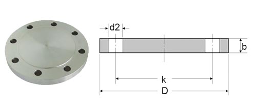
| NPS | Dimension Of Flange | Parameter Of Screw | Approx. Flange Weight In KG | |||
| Flanges Diameter | Thickness of Flanges | Diameter of Bolt Circle | Number of holes | Diameter of Bolt Holes | ||
| DIN | D | b | k | X | d2 | KG/PCS |
| 10 | 75 | 12 | 50 | 4 | 11 | 0.38 |
| 15 | 80 | 12 | 55 | 4 | 11 | 0.44 |
| 20 | 90 | 14 | 65 | 4 | 11 | 0.66 |
| 25 | 100 | 14 | 75 | 4 | 11 | 0.82 |
| 32 | 120 | 14 | 90 | 4 | 14 | 1.18 |
| 40 | 130 | 14 | 100 | 4 | 14 | 1.39 |
| 50 | 140 | 14 | 110 | 4 | 14 | 1.62 |
| 65 | 160 | 14 | 130 | 4 | 14 | 2.14 |
| 80 | 190 | 16 | 150 | 4 | 48 | 3.43 |
| 100 | 210 | 16 | 170 | 4 | 18 | 4.22 |
| 125 | 240 | 18 | 200 | 8 | 18 | 6.1 |
| 150 | 265 | 18 | 225 | 8 | 18 | 7.51 |
| 175 | 295 | 20 | 255 | 8 | 18 | 10.41 |
| 200 | 320 | 20 | 280 | 8 | 18 | 12.31 |
| 250 | 375 | 22 | 335 | 12 | 18 | 18.55 |
| 300 | 440 | 22 | 395 | 12 | 22 | 25.47 |
| 350 | 490 | 22 | 445 | 12 | 22 | 31.78 |
| 400 | 540 | 22 | 495 | 16 | 22 | 38.5 |
| 500 | 645 | 24 | 600 | 20 | 22 | 60.13 |
| 600 | 755 | 28 | 705 | 20 | 26 | 96.07 |
| 700 | 860 | 30 | 810 | 24 | 26 | 133.8 |
| 800 | 975 | 32 | 920 | 24 | 30 | 183.29 |
| 900 | 1075 | 36 | 1020 | 24 | 30 | 251.7 |
| 1000 | 1175 | 42 | 1120 | 28 | 30 | 350.98 |
DIN 2527 PN10 Blind Flange Dimensions
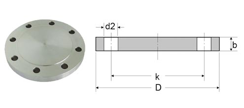
| DIN 2527 PN10 Blind Flange Dimensions | |||||||
| Rated NPS Diameter | Flange | Screws/NPT | Weight in kg (7,85 Kg/dm3) |
||||
| D | b | k | Number | Thread | d2 | Shape B | |
| Kilogram | |||||||
| 15 | 95 | 14 | 65 | 4 | M 12 | 14 | 0,72 |
| 20 | 105 | 16 | 75 | 1,01 | |||
| 25 | 115 | 16 | 85 | 1,23 | |||
| 32 | 140 | 16 | 100 | M 16 | 18 | 1,8 | |
| 40 | 150 | 16 | 110 | 2,09 | |||
| 50 | 165 | 18 | 125 | 2,88 | |||
| 65 | 185 | 18 | 145 | 3,66 | |||
| 80 | 200 | 20 | 160 | 4,77 | |||
| 100 | 220 | 20 | 180 | 8 | 5,65 | ||
| 125 | 250 | 22 | 210 | 8,42 | |||
| 150 | 285 | 22 | 240 | M 20 | 22 | 10,4 | |
| 200 | 340 | 24 | 295 | 16,5 | |||
| 250 | 395 | 26 | 350 | 12 | 24 | ||
| 300 | 445 | 26 | 400 | 30,9 | |||
| 350 | 505 | 26 | 460 | 16 | 40,6 | ||
| 400 | 565 | 26 | 515 | M 24 | 26 | 49,4 | |
| 500 | 670 | 28 | 620 | 20 | 75 | ||
DIN 2527 PN16 Blind Flange Dimensions
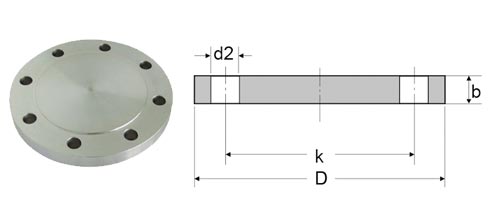
| DIN 2527 PN16 Blind Flange Dimensions | |||||||
| Rated Diameter |
Dimensions Of Flange | Screws/Threaded | Weight In KG (7,85 Kg/dm3) |
||||
| D | b | k | Number | Thread | d2 | Shape B | |
| Kg | |||||||
| 15 | 95 | 14 | 65 | 4 | M 12 | 14 | 0,72 |
| 20 | 105 | 16 | 75 | 1,01 | |||
| 25 | 115 | 16 | 85 | 1,23 | |||
| 32 | 140 | 16 | 100 | M 16 | 18 | 1,8 | |
| 40 | 150 | 16 | 110 | 2,09 | |||
| 50 | 165 | 18 | 125 | 2,88 | |||
| 65 | 185 | 18 | 145 | 3,66 | |||
| 80 | 200 | 20 | 160 | 8 | 4,77 | ||
| 100 | 220 | 20 | 180 | 5,65 | |||
| 125 | 250 | 22 | 210 | 8,42 | |||
| 150 | 285 | 22 | 240 | M 20 | 22 | 10,4 | |
| 200 | 340 | 24 | 295 | 12 | 16,1 | ||
| 250 | 405 | 26 | 355 | M 24 | 26 | 24,9 | |
| 300 | 460 | 28 | 410 | 35,1 | |||
| 350 | 520 | 30 | 470 | 16 | 47,8 | ||
| 400 | 580 | 32 | 525 | M 27 | 30 | 63,5 | |
| 500 | 715 | 36 | 650 | 20 | M 30 | 33 | 102 |
DIN 2527 PN25 Blind Flange Dimensions
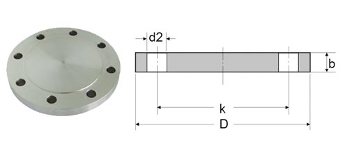
| Nominal Flanges Diameter | DIN 2527 PN25 Blind Flanges Pressure (PN) | |||||
|---|---|---|---|---|---|---|
| **Nominal Pipe Size (BSP) | PN6 | PN10 | PN16 | PN25 | PN40 | |
|
DN 10 |
75 |
90 |
90 |
90 |
90 |
O.D. |
|
3/8" |
50 |
60 |
60 |
60 |
60 |
PCD (circle Of bolt) |
|
|
4 x 11 |
4 x 14 |
4 x 14 |
4 x 14 |
4 x 14 |
# of holes x diameter of holes |
|
DN 15 |
80 |
95 |
95 |
95 |
95 |
O.D. |
|
1/2" |
55 |
65 |
65 |
65 |
65 |
PCD (circle Of bolt) |
|
|
4 x 11 |
4 x 14 |
4 x 14 |
4 x 14 |
4 x 14 |
# of holes x diameter of holes |
|
DN 20 |
90 |
105 |
105 |
105 |
105 |
O.D. |
|
3/4" |
65 |
75 |
75 |
75 |
75 |
PCD (circle Of bolt) |
|
|
4 x 11 |
4 x 14 |
4 x 14 |
4 x 14 |
4 x 14 |
# of holes x diameter of holes |
|
DN 25 |
100 |
115 |
115 |
115 |
115 |
O.D. |
|
1" |
75 |
85 |
85 |
85 |
85 |
PCD (circle Of bolt) |
|
|
4 x 11 |
4 x 14 |
4 x 14 |
4 x 14 |
4 x 14 |
# of holes x diameter of holes |
|
DN 32 |
120 |
140 |
140 |
140 |
140 |
O.D. |
|
1 1/4" |
90 |
100 |
100 |
100 |
100 |
PCD (circle Of bolt) |
|
|
4 x 14 |
4 x 18 |
4 x 18 |
4 x 18 |
4 x 18 |
# of holes x diameter of holes |
|
DN 40 |
130 |
150 |
150 |
150 |
150 |
O.D. |
|
1 1/2" |
100 |
110 |
110 |
110 |
110 |
PCD (circle Of bolt) |
|
|
4 x 14 |
4 x 18 |
4 x 18 |
4 x 18 |
4 x 18 |
# of holes x diameter of holes |
|
DN 50 |
140 |
165 |
165 |
165 |
165 |
O.D. |
|
2" |
110 |
125 |
125 |
125 |
125 |
PCD (circle Of bolt) |
|
|
4 x 14 |
4 x 18 |
4 x 18 |
4 x 18 |
4 x 18 |
# of holes x diameter of holes |
|
DN 65 |
160 |
185 |
185 |
185 |
185 |
O.D. |
|
2 1/2" |
130 |
145 |
145 |
145 |
145 |
PCD (circle Of bolt) |
|
|
4 x 14 |
4 x 18 |
4 x 18 |
8 x 18 |
8 x 18 |
# of holes x diameter of holes |
|
DN 80 |
190 |
200 |
200 |
200 |
200 |
O.D. |
|
3" |
150 |
160 |
160 |
160 |
160 |
PCD (circle Of bolt) |
|
|
4 x 18 |
8 x 18 |
8 x 18 |
8 x 18 |
8 x 18 |
# of holes x diameter of holes |
|
DN 100 |
210 |
220 |
220 |
235 |
235 |
O.D. |
|
4" |
170 |
180 |
180 |
190 |
190 |
PCD (circle Of bolt) |
|
|
4 x 18 |
8 x 18 |
8 x 18 |
8 x 22 |
8 x 22 |
# of holes x diameter of holes |
|
DN 125 |
240 |
250 |
250 |
270 |
270 |
O.D. |
|
5" |
200 |
210 |
210 |
220 |
220 |
PCD (circle Of bolt) |
|
|
8 x 18 |
8 x 18 |
8 x 18 |
8 x 26 |
8 x 26 |
# of holes x diameter of holes |
|
DN 150 |
265 |
285 |
285 |
300 |
300 |
O.D. |
|
6" |
225 |
240 |
240 |
250 |
250 |
PCD (circle Of bolt) |
|
|
8 x 18 |
8 x 22 |
8 x 22 |
8 x 26 |
8 x 26 |
# of holes x diameter of holes |
|
DN 175 |
|
315 |
315 |
330 |
350 |
O.D. |
|
7" |
|
270 |
270 |
280 |
295 |
PCD (circle Of bolt) |
|
|
|
8 x 22 |
8 x 22 |
12 x 26 |
12 x 30 |
# of holes x diameter of holes |
|
DN 200 |
320 |
340 |
340 |
360 |
375 |
O.D. |
|
8" |
280 |
295 |
295 |
310 |
320 |
PCD (circle Of bolt) |
|
|
8 x 18 |
8 x 22 |
12 x 22 |
12 x 26 |
12 x 30 |
# of holes x diameter of holes |
|
DN 250 |
375 |
395 |
405 |
425 |
450 |
O.D. |
|
10" |
335 |
350 |
355 |
370 |
385 |
PCD (circle Of bolt) |
|
|
12 x 18 |
12 x 22 |
12 x 26 |
12 x 30 |
12 x 33 |
# of holes x diameter of holes |
|
DN 300 |
440 |
445 |
460 |
485 |
515 |
O.D. |
|
12" |
395 |
400 |
410 |
430 |
450 |
PCD (circle Of bolt) |
|
|
12 x 22 |
12 x 22 |
12 x 26 |
16 x 30 |
16 x 33 |
# of holes x diameter of holes |
|
DN 350 |
490 |
505 |
520 |
555 |
580 |
O.D. |
|
14" |
445 |
460 |
470 |
490 |
510 |
PCD (circle Of bolt) |
|
|
12 x 22 |
16 x 22 |
16 x 26 |
16 x 33 |
16 x 36 |
# of holes x diameter of holes |
|
DN 400 |
540 |
565 |
580 |
620 |
660 |
O.D. |
|
16" |
495 |
515 |
525 |
550 |
585 |
PCD (circle Of bolt) |
|
|
16 x 22 |
16 x 26 |
16 x 30 |
16 x 36 |
16 x 39 |
# of holes x diameter of holes |
|
DN 500 |
645 |
670 |
715 |
730 |
755 |
O.D. |
|
20" |
600 |
620 |
650 |
660 |
670 |
PCD (circle Of bolt) |
|
|
20 x 22 |
20 x 26 |
20 x 33 |
20 x 36 |
20 x 42 |
# of holes x diameter of holes |
|
DN 600 |
755 |
780 |
840 |
845 |
|
O.D. |
|
24" |
705 |
725 |
770 |
770 |
|
PCD (circle Of bolt) |
|
|
20 x 24 |
20 x 27 |
20 x 33 |
20 x 36 |
|
# of holes x diameter of holes |
DIN 2527 PN40 Blind Flange Dimensions

| NPS | Dimension Of Flange | Parameter Of Screw | Weight Table Of Approx. Flange | |||
| Diameter Of Flanges | Thk of Flange | Thickness of Bolt Circle | Number of holes | Diameter of Bolt Holes | ||
| DIN | D | b | k | X | d2 | KG/PCS |
| 10 | 90 | 16 | 60 | 4 | 14 | 0.72 |
| 15 | 95 | 16 | 65 | 4 | 14 | 0.81 |
| 20 | 105 | 18 | 75 | 4 | 14 | 1.14 |
| 25 | 115 | 18 | 85 | 4 | 14 | 1.38 |
| 32 | 140 | 18 | 100 | 4 | 18 | 2.03 |
| 40 | 150 | 18 | 110 | 4 | 18 | 2.35 |
| 50 | 165 | 20 | 125 | 4 | 18 | 3.2 |
| 65 | 185 | 22 | 145 | 8 | 18 | 4.29 |
| 80 | 200 | 24 | 160 | 8 | 18 | 5.54 |
| 100 | 235 | 24 | 190 | 8 | 22 | 7.6 |
| 125 | 270 | 26 | 220 | 8 | 26 | 10.82 |
| 150 | 300 | 28 | 250 | 8 | 26 | 14.6 |
| 175 | 350 | 32 | 295 | 12 | 30 | 22.04 |
| 200 | 375 | 34 | 320 | 12 | 30 | 27.21 |
| 250 | 450 | 38 | 385 | 12 | 33 | 44.38 |
| 300 | 515 | 42 | 450 | 16 | 33 | 64.17 |
| 350 | 580 | 46 | 510 | 16 | 36 | 89.52 |
| 400 | 660 | 50 | 585 | 16 | 39 | 126.76 |
| 500 | 755 | 56 | 670 | 20 | 42 | 184.63 |
| 600 | 890 | 62 | 795 | 20 | 48 | 285.17 |
| 700 | 995 | 64 | 900 | 24 | 48 | 368.83 |
| 800 | 1140 | 70 | 1030 | 24 | 56 | 528.39 |
| 900 | 1250 | 76 | 1140 | 28 | 56 | 690.99 |
Din 2633 Blind Flange Dimensions
| welding flanges | Diameter Of Pitch Circle | Holes Of Thread | |
| DN 20/26,9 millimeter | 75 millimeter | 4 x 14 millimeter | |
| DN 25/33,7 millimeter | 85 millimeter | 4 x 14 millimeter | |
| DN 32/42,4 mm | 100 mm | 4 x 18 mm | |
| DN 40/48,3 mm | 110 mm | 4 x 18 mm | |
| DN 50/60,3 mm | 125 mm | 4 x 18 mm | |
| DN 65/76,1 mm | 145 mm | 4 x 18 mm | |
| DN 80/88,9 mm | 160 mm | 8 x 18 mm | |
| DN 100/108 or 114,3 mm | 180 mm | 8 x 18 mm | |
| DN 125/133 or 139,7 mm | 210 mm | 8 x 18 mm | |
| DN 150/159 or 168,3 mm | 240 mm | 8 x 22 mm | |
| DN 200/219,1 mm | 295 mm | 12 x 22 mm | |
| DN 250/273 mm | 355 mm | 12 x 26 mm |
Din 2576 Blind Flange Dimensions
| NPS | Pipe Diameter | Dimension Of Flanges | Bolts And Nuts | Approx. Flanges Weight | |||||
| Flanges Inside Daimeter | Flanges Daimeter | Thickness of Flanges | Daimeter of Bolt Circle | Number of Holes | Daimeter of Bolt Holes | ||||
| DN | ISO | DIN | d5 | D | b | k | d2 | KG /PCS | |
| 10 | - | 14 | 14.5 | 90 | 14 | 60 | 4 | 14 | 0.61 |
| 17.2 | - | 17.7 | 90 | 14 | 60 | 4 | 14 | 0.6 | |
| 15 | - | 20 | 21 | 95 | 14 | 65 | 4 | 14 | 0.67 |
| 21.3 | - | 22 | 95 | 14 | 65 | 4 | 14 | 0.67 | |
| 20 | - | 25 | 26 | 105 | 16 | 75 | 4 | 14 | 0.94 |
| 26.9 | - | 27.6 | 105 | 16 | 75 | 4 | 14 | 0.94 | |
| 25 | - | 30 | 31 | 115 | 16 | 85 | 4 | 14 | 1.13 |
| 33.7 | - | 34.4 | 115 | 16 | 85 | 4 | 14 | 1.11 | |
| 32 | - | 38 | 39 | 140 | 16 | 100 | 4 | 18 | 1.66 |
| 42.4 | - | 43.1 | 140 | 16 | 100 | 4 | 18 | 1.62 | |
| 40 | - | 44.5 | 45.5 | 150 | 16 | 110 | 4 | 18 | 1.89 |
| 48.3 | - | 49 | 150 | 16 | 110 | 4 | 18 | 1.85 | |
| 50 | - | 57 | 58.1 | 165 | 18 | 125 | 4 | 18 | 2.5 |
| 60.3 | - | 61.1 | 165 | 18 | 125 | 4 | 18 | 2.46 | |
| 65 | 76.1 | - | 77.1 | 185 | 18 | 145 | 4 | 18 | 2.99 |
| 80 | 88.9 | - | 90.3 | 200 | 20 | 160 | 8 | 18 | 3.61 |
| 100 | - | 108 | 109.6 | 220 | 20 | 180 | 8 | 18 | 4.17 |
| 114.3 | - | 115.9 | 220 | 20 | 180 | 8 | 18 | 3.99 | |
| 125 | - | 133 | 134.8 | 250 | 22 | 210 | 8 | 18 | 5.66 |
| 139.7 | - | 141.6 | 250 | 22 | 210 | 8 | 18 | 5.41 | |
| 150 | - | 159 | 161.1 | 285 | 22 | 240 | 8 | 22 | 6.97 |
| 168.3 | - | 170.5 | 285 | 22 | 240 | 8 | 22 | 6.55 | |
| 175 | 193.7 | - | 196.1 | 315 | 24 | 270 | 8 | 22 | 8.42 |
| 200 | 219.1 | - | 221.8 | 340 | 24 | 295 | 8 | 22 | 9.28 |
| 250 | - | 267 | 270.2 | 395 | 26 | 350 | 12 | 22 | 12.36 |
| 273 | - | 276.2 | 395 | 26 | 350 | 12 | 22 | 11.85 | |
| 300 | 323.9 | - | 327.6 | 445 | 26 | 400 | 12 | 22 | 13.61 |
| 350 | 355.6 | - | 359.7 | 505 | 28 | 460 | 16 | 22 | 20.35 |
| - | 368 | 372.2 | 505 | 28 | 460 | 16 | 22 | 18.77 | |
| 400 | 406.4 | - | 411 | 565 | 32 | 515 | 18 | 26 | 27.52 |
| - | 419 | 423.7 | 565 | 32 | 515 | 18 | 26 | 35.43 | |
| 450 | 457 | - | 462.3 | 615 | 38 | 565 | 20 | 26 | 35.11 |
| 500 | 508 | - | 613.6 | 670 | 38 | 620 | 20 | 26 | 40.2 |
| 600 | 610 | - | 615.5 | 780 | 40 | 725 | 20 | 26 | 51.87 |
Din 2501 Blind Flange Dimensions

| NPS (Normal Pipe Size) | Dimension of Flanges | Diameter Of Flanges | Inside Daimeter Of Flanges | Thickness of Flange | Bolt Cirlce Diameter | Number of holes | Diameter of Bolt Holes | Weight in kg | |
|---|---|---|---|---|---|---|---|---|---|
| Plate | Blind | ||||||||
| DN | Pipe | D | D5 | B | K | holes | D2 | KG | KG |
| 15 | 21.30 | 95 | 22.00 | 14 | 65 | 4 | 14 | 0.67 | 0.71 |
| 20 | 26.90 | 105 | 27.60 | 16 | 75 | 4 | 14 | 0.93 | 1.01 |
| 25 | 33.70 | 115 | 34.40 | 16 | 85 | 4 | 14 | 1.11 | 1.23 |
| 32 | 42.40 | 140 | 43.10 | 16 | 100 | 4 | 18 | 1.62 | 1.81 |
| 40 | 48.30 | 150 | 49.00 | 16 | 110 | 4 | 18 | 1.85 | 2.09 |
| 50 | 60.30 | 165 | 61.10 | 18 | 125 | 4 | 18 | 2.46 | 2.88 |
| 65 | 76.10 | 185 | 77.10 | 18 | 145 | 4 | 18 | 2.99 | 3.65 |
| 80 | 88.90 | 200 | 90.30 | 20 | 160 | 8 | 18 | 3.61 | 4.61 |
| 100 | 114.30 | 220 | 115.90 | 20 | 180 | 8 | 18 | 3.99 | 5.65 |
| 125 | 139.70 | 250 | 141.60 | 22 | 210 | 8 | 18 | 5.41 | 8.13 |
| 150 | 168.30 | 285 | 170.50 | 22 | 240 | 8 | 22 | 6.55 | 10.44 |
| 175 | 193.70 | 315 | 196.10 | 24 | 270 | 8 | 22 | 8.42 | |
| 200 | 219.10 | 340 | 221.80 | 24 | 295 | 12 | 22 | 8.97 | 16.48 |
| 250 | 273.00 | 405 | 276.20 | 26 | 355 | 12 | 26 | 12.76 | 23.99 |
| 300 | 323.90 | 460 | 327.60 | 28 | 410 | 12 | 26 | 16.60 | 30.73 |
| 350 | 355.60 | 520 | 359.70 | 30 | 470 | 16 | 26 | 24.08 | 42.56 |
| 400 | 406.40 | 580 | 411.00 | 32 | 525 | 16 | 30 | 30.20 | 60.68 |
| 450 | 457.00 | 640 | 462.30 | 38 | 585 | 20 | 30 | 41.67 | 71.74 |
| 500 | 508.00 | 715 | 513.60 | 38 | 650 | 20 | 33 | 52.87 | 96.4 |
| 600 | 610.00 | 840 | 616.50 | 42 | 770 | 20 | 36 | 77.58 | 145.6 |
| 700 | 711.00 | 910 | 716.00 | 44 | 840 | 24 | 36 | 77.13 | |
| 800 | 813.00 | 1025 | 818.00 | 50 | 950 | 24 | 39 | 106.35 | |
| 900 | 914.00 | 1125 | 920.00 | 54 | 1050 | 28 | 39 | 125.39 | |
| 1000 | 1016.00 | 1255 | 1022.00 | 60 | 1170 | 28 | 42 | 177.99 | |
Special Price For Type Of ASTM A105 Carbon Steel Flanges
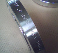
1 Inch, EN 10204-3.1, ASME B16.5 Blind Flanges
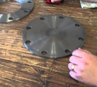
A350 LF2 CL1,CL1500, Ductile Iron Blind Flanges
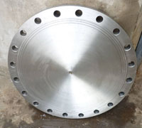
4 Inch, DN 100, PN 50 Class 300, ASME B16.5 BLRF Flanges
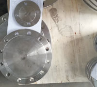
20 Inch, Class 150, Raised Face Blind Flanges
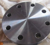
Size 10 Inch, RTJ, Class 2500, Aluminum Blind Flanges
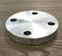
A182 304L 150LB, 6 inch, Stainless Steel Blind Flanges
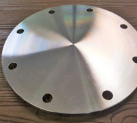
8 Inch, 600# Pressure, Grooved Blind Flanges
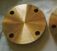
ANSI B16.5 PN16 to PN250, Copper Blind Flanges
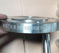
Mechanical Joint Blind Flange Used In Oil & Gas
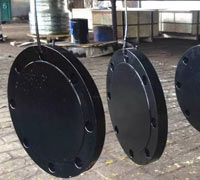
ASTM A105 Carbon Steel Blind Flanges
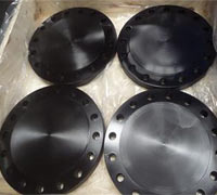
4 Inch, ASTM A105, Mild Steel Blind Flanges
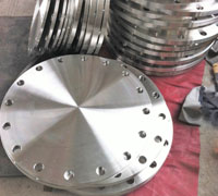
12 Inch, Class 300, Raised Face, Blrf Flanges
