ASTM A105 Flange
SA 105 Forged Flange and Carbon Steel Flanges manufacturer in India.
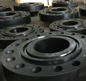
Carbon Steel Flanges Manufacturer In India
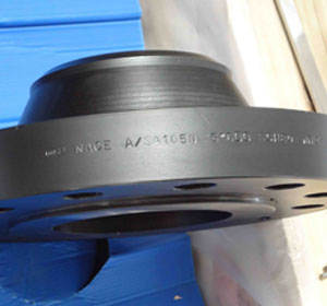
Carbon Steel Slip On Flanges
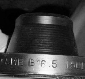
Carbon Steel Weld Neck Flanges
Table of contents
- What Is A105 Flange?
- What Use Of Carbon Steel Flanges In Piping?
- A105 Reducing Flange Can Be Used To Fit Pipes Of Two Different Diameters?
- Carbon Steel Pipe Flange Specifications
- CS Flanges Hs Code
- ASTM CS Flange Weight Chart
- Carbon Steel Flange Dimensions
- Class 150 Carbon Steel Flange Pressure Rating
- Class 300 Carbon Steel Flange Pressure Rating
- Carbon Steel Flange Size Chart
- Carbon Steel Flange Thickness
- Carbon Steel Flange Bolt Chart
- Carbon Steel Flange Torque Values
- Gasket For Carbon Steel Flange
- CS Pipe Flanges Tolerance Chart
- ASTM A105 Flanges Mechanical Properties
- ASTM A105 Flanges Chemical Composition
- Carbon Steel A105 Flanges Physical Properties
- ASTM A105 Flange Pressure Rating
- ASTM A105 150 Flange Dimensions
- ASTM A105 Class 300 Flange Dimensions
- ASTM A105 Weld Neck Flange Dimensions
- ASTM A105 Slip On Flange Dimensions
- SA105 Blind Flange Dimensions
- ASTM A105 Heat Treatment
- What Is The Difference Between A105 And A105N
- What Is The Difference Between A105 And A234
- Special Price For Type Of ASTM A105 Carbon Steel Flanges
What Is A105 Flange?
A105 Flange material is a forged carbon steel. ASTM A105 Flange Manufacturer in India produce different types and grades of the ASTM A105 Weld Neck Flange for sale. These are widely used in the market for non-critical applications. The ASTM A105 Blind Flange Material by default is not normalization heat treated. A105 Normalized Flanges are called the Ansi A105n Flanges where the n stands for normalization heat treatment. The heat treatment makes the Ansi A105 Flanges much harder and stronger.
What Use Of Carbon Steel Flanges In Piping?
These are developed and produced in different shapes and forms. Carbon Steel Flange with their welded necks are good picks for piping with bending stress crack risk. Carbon Steel Blind Flange cannot be used in extreme conditions because of the carbon steel material. They can stand up to certain levels but not overtake the high chromium molybdenum alloy counterparts of them. The prominent difference in A105 Vs A105n Flanges is the normalization heat treatment and the strength as a result. Their materials are the same, the composition is the same, and it is just the heat treatment that makes the differences.
A105 Reducing Flange Can Be Used To Fit Pipes Of Two Different Diameters?
A105 Reducing Flange can be used to fit pipes of two different diameters. One end of the reducing flange corresponds to the diameter of one pipe and the other end of the reducing flange corresponds to the diameter of the other pipe in the connection. Carbon Steel Weld Neck Flanges have the welded neck feature along with the heat treatment which makes them stronger. Carbon Steel Pipe Flanges could be used in applications such as food processing industry, chemical industry, oil and gas pipelines and more. Carbon Steel Slip On Flanges could be easily welded if needed. There are specifications by ASME as to which temperature and pressure the material could be welded at. ASTM A105 Blind Flange is a type that is used to seal the end of a pipe opening. These are forged flanges, so they stand the pressure without cracking. Also, this material is annealed so that it can withstand high temperatures in the application.
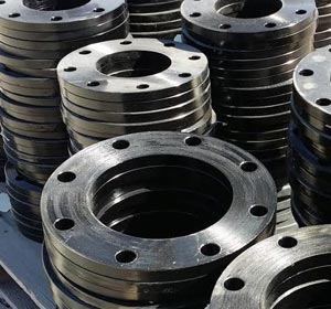
ASTM A105 Flange Manufacturer
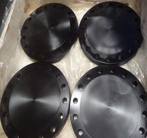
ASTM A105 Blind Flange
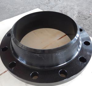
ASTM A105 Weld Neck Flange
Carbon Steel Pipe Flange Specifications
| Material Specification Of : | Carbon Steel Flanges And ASTM A105 Flanges |
|---|---|
| Standard Cover : | pressure ratings & temperature ratings, materials, marking, dimensions, weight, tolerances, testing |
| Contact Faces | RTJ (Ring Type Joint) Flanges, FF (Flat Face) Flanges, RF (Raised Face) Flanges, T/G (Tongue And Groove ) Flanges, M/F (Male And Female) Flanges |
| Size Chart | Normal Pipe Size 1/2 to NPS 24" |
| Thickness | Normal Pipe Size ≤ 18 |
| Bore Diameter | Normal Pipe ≤ 10 |
| Flanges Standards | EN 1092-1 Flanges, JIS Flanges, ASME B16.5 Flanges, ASME B16.47 type A Flanges, UNI Flanges, DIN Flanges |
| Pressure Rating | Class 150 To Class 2500 |
| High Temperature | Above 200°C (400°F) For Class 150 Or Above 400°C (750°F) |
| Low Temperature | Above -29 Degree C (−20°F) |
| Common Types Of Flanges: | Slip On (SORF) Flanges, Weld Neck (WNRF) Flanges, Blind (BLRF) Flanges, Lap Joint (Loose) Flanges, Threaded (NPT) Flanges, Socket-Weld (SWRF) Flanges |
| Special Types Of Flanges : | Nipoflange, Elboflange, Latroflange, Swivel Flanges, Expanding Flanges, Reducing Flanges, Weldoflange |
| Marking Standard | Name of Manufacturer Schedule Type of Flange Facing Nominal Pipe Size Pressure Class ASME B16 Designation |
| Bolt Type | high strength bolts medium strength bolts low strength bolts |
| European Standard Flanges | JIS B2220 Flanges (5k to 30k) and KS1503 flanges |
| Russian-Standard Flanges | GOST 12820 / 12821-80, DIN, UNI, EN 1092-1 |
| South African Standard Flanges | SANSflanges And SABS flanges |
| Surface Finish | smooth, concentric serrated, stock |
| Gaskets Types | Full Face Gasket Flanges Flat Ring Gasket Flanges Metallic Ring Gakset Flanges |
| Advantages Of Pipe Flange | Used to Connect Pipe System Easy Repair Pipe System Assembled Without Welding |
CS Flanges Hs Code
| 73072100 | Carbon Steel Flanges | 601 |
Check A105n Flanges Pressure Class and ASTM A105 Slip On/ Blind/ Weld Neck Flange Dimensions/ Temperature Ratings.
ASTM CS Flange Weight Chart
| Nominal Pipe Sizes (NPS) | Slip On (SORF) | Threaded (NPT) | Socket Weld (SWRF) | Lap Joint (Loose) | Blind (BLRF) | Weld Neck (WRNR) |
|---|---|---|---|---|---|---|
| ½ | 1 | 1 | 2 | 1 | 2 | 2 |
| ¾ | 2 | 2 | 2 | 2 | 2 | 2 |
| 1 | 2 | 2 | 2 | 2 | 2 | 3 |
| 1¼ | 3 | 3 | 3 | 3 | 3 | 3 |
| 1½ | 3 | 3 | 3 | 3 | 4 | 4 |
| 2 | 5 | 5 | 5 | 5 | 5 | 6 |
| 2½ | 8 | 8 | 8 | 8 | 7 | 10 |
| 3 | 9 | 9 | 9 | 9 | 9 | 11.5 |
| 3½ | 11 | 12 | 11 | 11 | 13 | 12 |
| 4 | 13 | 13 | 13 | 13 | 17 | 16.5 |
| 5 | 15 | 15 | 15 | 15 | 20 | 21 |
| 6 | 19 | 19 | 19 | 19 | 27 | 26 |
| 8 | 30 | 30 | 30 | 30 | 47 | 42 |
| 10 | 43 | 43 | 43 | 43 | 70 | 54 |
| 12 | 64 | 64 | 64 | 64 | 123 | 88 |
| 14 | 90 | 90 | 90 | 105 | 140 | 114 |
| 16 | 106 | 98 | 98 | 140 | 180 | 140 |
| 18 | 130 | 130 | 130 | 160 | 220 | 165 |
| 20 | 165 | 165 | 165 | 195 | 285 | 197 |
| 22 | 185 | 185 | 185 | 245 | 355 | 225 |
| 24 | 220 | 220 | 220 | 275 | 430 | 268 |
Carbon Steel Flange Dimensions
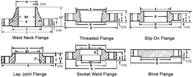
| NPS | O.D. of Flange | Flanges Thickness | Diameter of RF | Diameter of Hub at Base | Lengtd Tdru Hub | Bore or Diameter | Dia. of Hub at Bevel | Radius of Fillet | Deptd of Socket | |||
|---|---|---|---|---|---|---|---|---|---|---|---|---|
| Welding (WN) Neck | Slip-On (SORF) Threaded (NPT) Socket (SWRF) | Lap Joint (Loose) | Slip-on (SORF) Socket (SWRF) | Lap Joint (Loose) | ||||||||
| O | Q | R | X | Y | Y | Y | W | B | H | r | Z | |
| 1/2 | 3-1/2 | 7/16 | 1-3/8 | 1-3/16 | 1-7/8 | 5/8 | 5/8 | .88 | .90 | .84 | 1/8 | 3/8 |
| 3/4 | 3-7/8 | 1/2 | 1-11/16 | 1-1/2 | 2-1/16 | 5/8 | 5/8 | 1.09 | 1.11 | 1.05 | 1/8 | 7/16 |
| 1 | 4-1/4 | 9/16 | 2 | 1-15/16 | 2-3/16 | 11/16 | 11/16 | 1.36 | 1.38 | 1.32 | 1/8 | 1/2 |
| 1-1/4 | 4-5/8 | 5/8 | 2-1/2 | 2-5/16 | 2-1/4 | 13/16 | 13/16 | 1.70 | 1.72 | 1.66 | 3/16 | 9/16 |
| 1-1/2 | 5 | 11/16 | 2-7/8 | 2-9/16 | 2-7/16 | 7/8 | 7/8 | 1.95 | 1.97 | 1.90 | 1/4 | 5/8 |
| 2 | 6 | 3/4 | 3-5/8 | 3-1/16 | 2-1/2 | 1 | 1 | 2.44 | 2.46 | 2.38 | 5/16 | 11/16 |
| 2-1/2 | 7 | 7/8 | 4-1/8 | 3-9/16 | 2-3/4 | 1-1/8 | 1-1/8 | 2.94 | 2.97 | 2.88 | 5/16 | 3/4 |
| 3 | 7-1/2 | 15/16 | 5 | 4-1/4 | 2-3/4 | 1-3/16 | 1-3/16 | 3.57 | 3.60 | 3.50 | 3/8 | 13/16 |
| 3-1/2 | 8-1/2 | 15/16 | 5-1/2 | 4-13/16 | 2-13/16 | 1-1/4 | 1-1/4 | 4.07 | 4.10 | 4.00 | 3/8 | 7/8 |
| 4 | 9 | 15/16 | 6-3/16 | 5-5/16 | 3 | 1-5/16 | 1-5/16 | 4.57 | 4.60 | 4.50 | 7/16 | 15/16 |
| 5 | 10 | 15/16 | 7.5/16 | 6-7/16 | 3-1/2 | 1-7/16 | 1-7/16 | 5.66 | 5.69 | 5.56 | 7/16 | 15/16 |
| 6 | 11 | 1 | 8-1/2 | 7-9/16 | 3-1/2 | 1-9/16 | 1-9/16 | 6.72 | 6.75 | 6.63 | 1/2 | 1-1/16 |
| 8 | 13-1/2 | 1-1/8 | 10-5/8 | 9-11/16 | 4 | 1-3/4 | 1-3/4 | 8.72 | 8.75 | 8.63 | 1/2 | 1-1/4 |
| 10 | 16 | 1-3/16 | 12-3/4 | 12 | 4 | 1-15/16 | 1-15/16 | 10.88 | 10.92 | 10.75 | 1/2 | 1-5/16 |
| 12 | 19 | 1-1/4 | 15 | 14-3/8 | 4-1/2 | 2-3/16 | 2-3/16 | 12.88 | 12.92 | 12.75 | 1/2 | 1-9/16 |
| 14 | 21 | 1-3/8 | 16-1/4 | 15-3/4 | 5 | 2-1/4 | 3-1/8 | 14.14 | 14.18 | 14.00 | 1/2 | 1-5/8 |
| 16 | 23-1/2 | 1-7/16 | 18-1/2 | 18 | 5 | 2-1/2 | 3-7/16 | 16.16 | 16.19 | 16.00 | 1/2 | 1-3/4 |
| 18 | 25 | 1-9/16 | 21 | 19-7/8 | 5-1/2 | 2-11/16 | 3-13/16 | 18.18 | 18.20 | 18.00 | 1/2 | 1-15/16 |
| 20 | 27-1/2 | 1-11/16 | 23 | 22 | 5-11/16 | 2-7/8 | 4-1/16 | 20.20 | 20.25 | 20.00 | 1/2 | 2-1/8 |
| 24 | 32 | 1-7/8 | 27-1/4 | 26-1/8 | 6 | 3-1/4 | 4-3/8 | 24.25 | 24.25 | 24.00 | 1/2 | 2-1/2 |
CS Flange Weight Chart And ASTM A105 Flange Manufacturer In India, Carbon Steel Forged Flanges Bolt Size Chart In MM.
Class 150 Carbon Steel Flange Pressure Rating
| Temperature (in F°) | 150 LBS |
| < 100 | 285 |
| 200 | 260 |
| 300 | 230 |
| 400 | 200 |
| 500 | 170 |
| 600 | 140 |
| 650 | 125 |
| 700 | 110 |
| 750 | 95 |
| 800 | 80 |
| 850 | 65 |
| 900 | 50 |
| 950 | 35 |
| 1000 | 20 |
Class 300 Carbon Steel Flange Pressure Rating
|
Temperature (in F°)
|
Class 300 Flanges
|
|
100
|
740
|
|
200
|
680
|
|
300
|
655
|
|
400
|
635
|
|
500
|
605
|
|
600
|
570
|
|
650
|
550
|
|
700
|
530
|
|
750
|
505
|
|
800
|
410
|
|
850
|
320
|
|
900
|
230
|
|
950
|
135
|
|
1000
|
85
|
Carbon Steel Flange Size Chart
| DN In inches | Dimension | ASTM A105 Carbon Steel Flanges Dimensional Sizes 1/2 inches to 2 1/2 inches | ||||||||||||||
|---|---|---|---|---|---|---|---|---|---|---|---|---|---|---|---|---|
| 125 LBS 150 LBS | 300 LBS | 400 LBS | 600 LBS | 900 LBS | 1500 LBS | 2500 LBS | ||||||||||
| inches | millimeter | inches | millimeter | inches | millimeter | inches | millimeter | inches | millimeter | inches | millimeter | inches | millimeter | |||
| 1/2 | A | 3 1/2 | 88.9 | 3 3/4 | 95.2 | 3 3/4 | 95.2 | 3 3/4 | 95.2 | 4 3/4 | 121 | 4 3/4 | 121 | 5 1/4 | 133.4 | |
| b | 7/16 | 11.1 | 9/16 | 14.3 | 9/16 | 14.3 | 9/16 | 14.3 | 7/8 | 22.2 | 7/8 | 22.2 | 1 3/16 | 30.2 | ||
| D2 | 1 3/8 | 34.9 | 1 3/8 | 34.9 | 1 3/8 | 34.9 | 1 3/8 | 34.9 | 1 3/8 | 34.9 | 1 3/8 | 34.9 | 1 3/8 | 34.9 | ||
| D1 | 2 3/8 | 60.3 | 2 5/8 | 66.7 | 2 5/8 | 66.7 | 2 5/8 | 66.7 | 3 1/4 | 82.6 | 3 1/4 | 82.6 | 3 1/2 | 88.9 | ||
| n | 4 | 4 | 4 | 4 | 4 | 4 | 4 | 4 | 4 | 4 | 4 | - | 4 | 44 | ||
| d | 5/8 | 15.9 | 5/8 | 15.9 | 5/8 | 15.9 | 5/8 | 15.9 | 7/8 | 22.2 | 7/8 | 22.2 | 7/8 | 22.2 | ||
| 3/4 | A | 3 7/8 | 98.4 | 4 5/8 | 117.5 | 4 5/8 | 117.5 | 4 5/8 | 117.5 | 5 1/8 | 130 | 5 1/8 | 130 | 5 1/2 | 139.7 | |
| b | 1/2 | 12.7 | 5/8 | 15.9 | 5/8 | 15.9 | 5/8 | 15.9 | 1 | 25.4 | 1 | 25.4 | 1 1/4 | 31.8 | ||
| D2 | 1 11/16 | 42.9 | 1 11/16 | 42.9 | 1 11/16 | 42.9 | 1 11/16 | 42.9 | 1 11/16 | 42.9 | 1 11/16 | 42.9 | 1 11/16 | 42.9 | ||
| D1 | 2 3/4 | 69.8 | 3 1/4 | 82.5 | 3 1/4 | 82.5 | 3 1/4 | 82.5 | 3 1/2 | 88.9 | 3 1/2 | 88.9 | 3 3/4 | 95.2 | ||
| n | 4 | 4 | 4 | 4 | 4 | 4 | 4 | 4 | 4 | 4 | 4 | - | 4 | 44 | ||
| d | 5/8 | 15.9 | 3/4 | 19 | 3/4 | 19 | 3/4 | 19 | 7/8 | 22.2 | 7/8 | 22.2 | 7/8 | 22.2 | ||
| 1 | A | 4 1/4 | 108 | 4 7/8 | 123.8 | 4 7/8 | 123.8 | 4 7/8 | 123.8 | 5 7/8 | 149.2 | 5 7/8 | 149.2 | 6 1/4 | 159 | |
| b | 9/16 | 14.3 | 11/16 | 17.5 | 11/16 | 17.5 | 11/16 | 17.5 | 1 1/8 | 28.6 | 1 1/8 | 28.6 | 1 3/8 | 34.9 | ||
| D2 | 2 | 50.8 | 2 | 50.8 | 2 | 50.8 | 2 | 50.8 | 2 | 50.8 | 2 | 50.8 | 2 | 50.8 | ||
| D1 | 3 1/8 | 79.4 | 3 1/2 | 88.9 | 3 1/2 | 88.9 | 3 1/2 | 88.9 | 4 | 102 | 4 | 102 | 4 1/4 | 108 | ||
| n | 4 | 4 | 4 | 4 | 4 | 4 | 4 | 4 | 4 | 4 | 4 | 4 | 4 | 4 | ||
| d | 5/8 | 15.9 | 3/4 | 19 | 3/4 | 19 | 3/4 | 19 | 1 | 25.4 | 1 | 25.4 | 1 | 25.4 | ||
| 1 1/4 | A | 4 5/8 | 117.5 | 5 1/4 | 133.4 | 5 1/4 | 133.4 | 5 1/4 | 133.4 | 6 1/4 | 159 | 6 1/4 | 159 | 7 1/4 | 184.2 | |
| b | 5/8 | 15.9 | 3/4 | 19 | 13/16 | 20.6 | 13/16 | 20.6 | 1 1/8 | 28.6 | 1 1/8 | 28.6 | 1 1/2 | 38.1 | ||
| D2 | 2 1/2 | 63.5 | 2 1/2 | 63.5 | 2 1/2 | 63.5 | 2 1/2 | 63.5 | 2 1/2 | 63.5 | 2 1/2 | 63.5 | 2 1/2 | 63.5 | ||
| D1 | 3 1/2 | 88.9 | 3 7/8 | 98.4 | 3 7/8 | 98.4 | 3 7/8 | 98.4 | 4 3/8 | 111 | 4 3/8 | 111 | 5 1/8 | 130 | ||
| n | 4 | 4 | 4 | 4 | 4 | 4 | 4 | 4 | 4 | 4 | 4 | 4 | 4 | 4 | ||
| d | 5/8 | 15.9 | 3/4 | 19 | 3/4 | 19 | 3/4 | 19 | 1 | 25.4 | 1 | 25.4 | 1 1/8 | 28.6 | ||
| 1 1/2 | A | 5 | 127 | 6 1/8 | 155.6 | 6 1/8 | 155.6 | 6 1/8 | 155.6 | 7 | 177.8 | 7 | 177.8 | 8 | 203 | |
| b | 11/16 | 17.5 | 13/16 | 20.6 | 7/8 | 22.2 | 7/8 | 22.2 | 1 1/4 | 31.8 | 1 1/4 | 31.8 | 1 3/4 | 44.5 | ||
| D2 | 2 7/8 | 73 98 | 2 7/8 | 73 | 2 7/8 | 73 | 2 7/8 | 73 | 2 7/8 | 73 | 2 7/8 | 73 | 2 7/8 | 73 | ||
| D1 | 3 7/8 | 4 | 4 1/2 | 114 | 4 1/2 | 114 | 4 1/2 | 114 | 4 7/8 | 124 | 4 7/8 | 124 | 5 3/4 | 146 | ||
| n | 4 | 4 | 4 | 4 | 4 | 4 | 4 | 4 | 4 | 4 | 4 | 4 | 4 | 4 | ||
| d | 5/8 | . 15.9 | 7/8 | 22.2 | 7/8 | 22.2 | 7/8 | 22.2 | 1 1/8 | 28.6 | 1 1/8 | 28.6 | 1 1/4 | 31.8 | ||
| 2 | A | 6 | 152.4 | 6 1/2 | 165.1 | 6 1/2 | 165.1 | 6 1/2 | 165.1 | 8 1/2 | 215.9 | 8 1/2 | 215.9 | 9 1/4 | 234.9 | |
| b | 3/4 | 19 | 7/8 | 22.2 | 1 | 25.4 | 1 | 25.4 | 1 1/2 | 38.1 | 1 1/2 | 38.1 | 2 | 50.8 | ||
| D2 | 3 5/8 | 92.1 | 3 5/8 | 92.1 | 3 5/8 | 92.1 | 3 5/8 | 92.1 | 3 5/8 | 92.1 | 3 5/8 | 92.1 | 3 5/8 | 92.1 | ||
| D1 | 4 3/4 | 121 | 5 | 127 | 5 | 127 | 5 | 127 | 6 1/2 | 165.1 | 6 1/2 | 165.1 | 6 3/4 | 171 | ||
| n | 4 | 4 | 8 | 8 | 8 | 8 | 8 | 8 | 8 | 8 | 8 | 8 | 8 | 8 | ||
| d | 3/4 | 19 | 3/4 | 19 | 3/4 | 19 | 3/4 | 19 | 1 | 25.4 | 1 | 25.4 | 1 1/8 | 28.6 | ||
| 2 1/2 | A | 7 | 177.8 | 7 1/2 | 190.5 | 7 1/2 | 190.5 | 7 1/2 | 190.5 | 9 5/8 | 244 | 9 5/8 | 244 | 10 1/2 | 266.7 | |
| b | 7/8 | 22.2 | 1 | 25.4 | 1 1/8 | 28.6 | 1 1/8 | 28.6 | 1 5/8 | 41.3 | 1 5/8 | 41.3 | 2 1/4 | 57.2 | ||
| D2 | 4 1/8 | 104.8 | 4 1/8 | 104.8 | 4 1/8 | 104.8 | 4 1/8 | 104.8 | 4 1/8 | 105 | 4 1/8 | 105 | 4 1/8 | 105 | ||
| D1 | 5 1/2 | 139.7 | 5 7/8 | 149.2 | 5 7/8 | 149.2 | 5 7/8 | 149.2 | 7 1/2 | 190.5 | 7 1/2 | 190.5 | 7 3/4 | 197 | ||
| n | 4 | 4 | 8 | 8 | 8 | 8 | 8 | 8 | 8 | 8 | 8 | 8 | 8 | 8 | ||
| d | 3/4 | 19 | 7/8 | 22.2 | 7/8 | 22.2 | 7/8 | 22.2 | 1 1/8 | 28.6 | 1 1/8 | 28.6 | 1 1/4 | 31.8 | ||
Carbon Steel Weld Neck Flanges Tolerance Formula And ASTM A105 Flange Thickness Calculation.
Carbon Steel Flange Thickness
| Carbon Steel Flanges Wall Thickness | ||||||||||||||
|---|---|---|---|---|---|---|---|---|---|---|---|---|---|---|
| NPS (Normal Pipe Sizes) | Outside Daimeter (O.D.) | Schedule 10 | Schedule 20 | Schedule 30 | STD Wall | Schedule 40 | Schedule 60 | EXT Hvy | Schedule 80 | Schedule 100 | Schedule 120 | Schedule 140 | Schedule 160 | XX Hvy |
| ½ | 0.84 | 0.083 | ... | ... | 0.109 | 0.109 | ... | 0.147 | 0.147 | ... | ... | ... | 0.188 | 0.294 |
| ¾ | 1.05 | 0.083 | ... | ... | 0.113 | 0.113 | ... | 0.154 | 0.154 | ... | ... | ... | 0.219 | 0.308 |
| 1 | 1.315 | 0.109 | ... | ... | 0.133 | 0.133 | ... | 0.179 | 0.179 | ... | ... | ... | 0.25 | 0.358 |
| 1 ¼ | 1.66 | 0.109 | ... | ... | 0.14 | 0.14 | ... | 0.191 | 0.191 | ... | ... | ... | 0.25 | 0.382 |
| 1 ½ | 1.9 | 0.109 | ... | ... | 0.145 | 0.145 | ... | 0.2 | 0.2 | ... | ... | ... | 0.281 | 0.4 |
| 2 | 2.375 | 0.109 | ... | ... | 0.154 | 0.154 | ... | 0.218 | 0.218 | ... | ... | ... | 0.344 | 0.436 |
| 2 ½ | 2.875 | 0.12 | ... | ... | 0.203 | 0.203 | ... | 0.276 | 0.276 | ... | ... | ... | 0.375 | 0.552 |
| 3 | 3.5 | 0.12 | ... | ... | 0.216 | 0.216 | ... | 0.3 | 0.3 | ... | ... | ... | 0.438 | 0.6 |
| 3 ½ | 4 | 0.12 | ... | ... | 0.226 | 0.226 | ... | 0.318 | 0.318 | ... | ... | ... | ... | 0.636 |
| 4 | 4.5 | 0.12 | ... | ... | 0.237 | 0.237 | ... | 0.337 | 0.337 | ... | 0.438 | ... | 0.531 | 0.674 |
| 5 | 5.563 | 0.134 | ... | ... | 0.258 | 0.258 | ... | 0.375 | 0.375 | ... | 0.5 | ... | 0.625 | 0.75 |
| 6 | 6.625 | 0.134 | ... | ... | 0.28 | 0.28 | ... | 0.432 | 0.432 | ... | 0.562 | ... | 0.719 | 0.864 |
| 8 | 8.625 | 0.148 | 0.25 | 0.277 | 0.322 | 0.322 | 0.406 | 0.5 | 0.5 | 0.594 | 0.719 | 0.812 | 0.906 | 0.875 |
| 10 | 10.75 | 0.165 | 0.25 | 0.307 | 0.365 | 0.365 | 0.5 | 0.5 | 0.594 | 0.719 | 0.844 | 1 | 1.125 | 1 |
| 12 | 12.75 | 0.18 | 0.25 | 0.33 | 0.375 | 0.406 | 0.562 | 0.5 | 0.688 | 0.844 | 1 | 1.125 | 1.312 | 1 |
| 14 | 14 | 0.25 | 0.312 | 0.375 | 0.375 | 0.438 | 0.594 | 0.5 | 0.75 | 0.938 | 1.094 | 1.25 | 1.406 | ... |
| 16 | 16 | 0.25 | 0.312 | 0.375 | 0.375 | 0.5 | 0.656 | 0.5 | 0.844 | 1.031 | 1.219 | 1.438 | 1.594 | ... |
| 18 | 18 | 0.25 | 0.312 | 0.438 | 0.375 | 0.562 | 0.75 | 0.5 | 0.938 | 1.156 | 1.375 | 1.562 | 1.781 | ... |
| 20 | 20 | 0.25 | 0.375 | 0.5 | 0.375 | 0.594 | 0.812 | 0.5 | 1.031 | 1.281 | 1.5 | 1.75 | 1.969 | ... |
| 22 | 22 | 0.25 | ... | ... | 0.375 | ... | ... | 0.5 | ... | ... | .... | .... | .... | .... |
| 24 | 24 | 0.25 | 0.375 | 0.562 | 0.375 | 0.688 | 0.969 | 0.5 | 1.219 | 1.531 | 1.812 | 2.062 | 2.344 | .... |
| 26 | 26 | .... | .... | .... | 0.375 | .... | .... | 0.5 | .... | .... | .... | .... | .... | .... |
| 30 | 30 | 0.312 | 0.5 | 0.625 | 0.375 | .... | .... | 0.5 | .... | .... | .... | .... | .... | .... |
| 36 | 36 | 0.312 | 0.5 | 0.625 | 0.375 | 0.75 | .... | 0.5 | .... | .... | .... | .... | .... | .... |
| 40 | 40 | .... | .... | .... | 0.375 | .... | .... | 0.5 | .... | .... | .... | .... | .... | .... |
| 42 | 42 | …….. | …….. | …….. | 0.375 | …….. | …….. | 0.5 | …….. | …….. | …….. | …….. | …….. | …….. |
| 48 | 48 | …….. | …….. | …….. | 0.375 | …….. | …….. | 0.5 | …….. | …….. | …….. | …….. | …….. | …….. |
Carbon Steel Flange Bolt Chart
| Class 150 Flanges | Class 300 Flanges | Class 600 Flanges | ||||||||||
|---|---|---|---|---|---|---|---|---|---|---|---|---|
| NPS | # Bolts And Studs | Diameter of Bolts And Studs | Stud Length | # Bolts And Studs | Diameter of Bolts And Studs | Stud Length | # Bolts And Studs | Diameter of Bolts And Studs | Stud Length | |||
| 1/16 RF | RTJ | 1/16 RF | RTJ | 1/4 RF | RTJ | |||||||
| 1/2 | 4 | 0.50 | 2-1/4 | – | 4 | 0.50 | 2-1/2 | 3 | 4 | 0.50 | 3 | 3 |
| 3/4 | 4 | 0.50 | 2-1/2 | – | 4 | 0.63 | 3 | 3-1/2 | 4 | 0.63 | 3-1/2 | 3-1/2 |
| 1 | 4 | 0.50 | 2-1/2 | 3 | 4 | 0.63 | 3 | 3-1/2 | 4 | 0.63 | 3-1/2 | 3-1/2 |
| 1-1/4 | 4 | 0.50 | 2-3/4 | 3-1/4 | 4 | 0.63 | 3-1/4 | 3-3/4 | 4 | 0.63 | 3-3/4 | 3-3/4 |
| 1-1/2 | 4 | 0.50 | 2-3/4 | 3-1/4 | 4 | 0.75 | 3-1/2 | 4 | 4 | 0.75 | 4-1/4 | 4-1/4 |
| 2 | 4 | 0.63 | 3-1/4 | 3-3/4 | 8 | 0.63 | 3-1/2 | 4 | 8 | 0.63 | 4-1/4 | 4-1/4 |
| 2-1/2 | 4 | 0.63 | 3-1/2 | 4 | 8 | 0.75 | 4 | 4-1/2 | 8 | 0.75 | 4-3/4 | 4-3/4 |
| 3 | 4 | 0.63 | 3-1/2 | 4 | 8 | 0.75 | 4-1/4 | 4-3/4 | 8 | 0.75 | 5 | 5 |
| 3-1/2 | 8 | 0.63 | 3-1/2 | 4 | 8 | 0.75 | 4-1/4 | 5 | 8 | 0.88 | 5-1/2 | 5-1/2 |
| 4 | 8 | 0.63 | 3-1/2 | 4 | 8 | 0.75 | 4-1/2 | 5 | 8 | 0.88 | 5-3/4 | 5-3/4 |
| 5 | 8 | 0.75 | 3-3/4 | 4-1/4 | 8 | 0.75 | 4-3/4 | 5-1/4 | 8 | 1.00 | 6-1/2 | 6-1/2 |
| 6 | 8 | 0.75 | 4 | 4-1/2 | 12 | 0.75 | 4-3/4 | 5-1/2 | 12 | 1.00 | 6-3/4 | 6-3/4 |
| 8 | 8 | 0.75 | 4-1/4 | 4-3/4 | 12 | 0.88 | 5-1/2 | 6 | 12 | 1.13 | 7-1/2 | 7-3/4 |
| 10 | 12 | 0.88 | 4-1/2 | 5 | 16 | 1.00 | 6-1/4 | 6-3/4 | 16 | 1.25 | 8-1/2 | 8-1/2 |
| 12 | 12 | 0.88 | 4-3/4 | 5-1/4 | 16 | 1.13 | 6-3/4 | 7-1/4 | 20 | 1.25 | 8-3/4 | 8-3/4 |
| 14 | 12 | 1.00 | 5-1/4 | 5-3/4 | 20 | 1.13 | 7 | 7-1/2 | 20 | 1.38 | 9-1/4 | 9-1/4 |
| 16 | 16 | 1.00 | 5-1/4 | 5-3/4 | 20 | 1.25 | 7-1/2 | 8 | 20 | 1.50 | 10 | 10 |
| 18 | 16 | 1.13 | 5-3/4 | 6-1/4 | 24 | 1.25 | 7-3/4 | 8-1/4 | 20 | 1.63 | 10-3/4 | 10-3/4 |
| 20 | 20 | 1.13 | 6-1/4 | 6-3/4 | 24 | 1.25 | 8 | 8-3/4 | 24 | 1.63 | 11-1/4 | 11-1/2 |
| 24 | 20 | 1.25 | 6-3/4 | 7-1/4 | 24 | 1.50 | 9 | 10 | 24 | 1.88 | 13 | 13-1/4 |
| Class 900 Flanges | Class 1500 Flanges | Class 2500 Flanges | ||||||||||
|---|---|---|---|---|---|---|---|---|---|---|---|---|
| NPS | # Bolts And Studs | Diameter of Bolts And Studs | Stud Length | # Bolts And Studs | Diameter of Bolts And Studs | Stud Length | # Bolts And Studs | Diameter of Bolts And Studs | Stud Length | |||
| 1/4 RF | RTJ | 1/4 RF | RTJ | 1/4 RF | RTJ | |||||||
| 1/2 | 4 | 0.75 | 4-1/4 | 4-1/4 | 4 | 0.75 | 4-1/4 | 4-1/4 | 4 | 0.75 | 4-3/4 | 4-3/4 |
| 3/4 | 4 | 0.75 | 4-1/2 | 4-1/2 | 4 | 0.75 | 4-1/2 | 4-1/2 | 4 | 0.75 | 5 | 5 |
| 1 | 4 | 0.88 | 5 | 5 | 4 | 0.88 | 5 | 5 | 4 | 0.88 | 5-1/2 | 5-1/2 |
| 1-1/4 | 4 | 0.88 | 5 | 5 | 4 | 0.88 | 5 | 5 | 4 | 1.00 | 6 | 6 |
| 1-1/2 | 4 | 1.00 | 5-1/2 | 5-1/2 | 4 | 1.00 | 5-1/2 | 5-1/2 | 4 | 1.13 | 6-3/4 | 6-3/4 |
| 2 | 8 | 0.88 | 5-3/4 | 5-3/4 | 8 | 0.88 | 5-3/4 | 5-3/4 | 8 | 1.00 | 7 | 7 |
| 2-1/2 | 8 | 1.00 | 6-1/4 | 6-1/4 | 8 | 1.00 | 6-1/4 | 6-1/4 | 8 | 1.13 | 7-3/4 | 8 |
| 3 | 8 | 0.88 | 5-3/4 | 5-3/4 | 8 | 1.13 | 7 | 7 | 8 | 1.25 | 8-3/4 | 9 |
| 4 | 8 | 1.13 | 6-3/4 | 6-3/4 | 8 | 1.25 | 7-3/4 | 7-3/4 | 8 | 1.50 | 10 | 10-1/4 |
| 5 | 8 | 1.25 | 7-1/2 | 7-1/2 | 8 | 1.50 | 9-3/4 | 9-3/4 | 8 | 1.75 | 11-3/4 | 12-1/4 |
| 6 | 12 | 1.13 | 7-1/2 | 7-3/4 | 12 | 1.38 | 10-1/4 | 10-1/2 | 8 | 2.00 | 13-1/2 | 14 |
| 8 | 12 | 1.38 | 8-3/4 | 8-3/4 | 12 | 1.63 | 11-1/2 | 11-3/4 | 12 | 2.00 | 15 | 15-1/2 |
| 10 | 16 | 1.38 | 9-1/4 | 9-1/4 | 12 | 1.88 | 13-1/4 | 13-1/2 | 12 | 2.50 | 19-1/4 | 20 |
| 12 | 20 | 1.38 | 10 | 10 | 16 | 2.00 | 14-3/4 | 15-1/4 | 12 | 2.75 | 21-1/4 | 22 |
| 14 | 20 | 1.50 | 10-3/4 | 11 | 16 | 2.25 | 16 | 16-3/4 | – | – | – | – |
| 16 | 20 | 1.63 | 11-1/4 | 11-1/2 | 16 | 2.50 | 17-1/2 | 18-1/2 | – | – | – | – |
| 18 | 20 | 1.88 | 12-3/4 | 13-1/4 | 16 | 2.75 | 19-1/2 | 20-3/4 | – | – | – | – |
| 20 | 20 | 2.00 | 13-3/4 | 14-1/4 | 16 | 3.00 | 21-1/4 | 22-1/4 | – | – | – | – |
| 24 | 20 | 2.50 | 17-1/4 | 18 | 16 | 3.50 | 24-1/4 | 25-1/2 | – | – | – | – |
Carbon Steel Flange Torque Values
| Size in Inches | Size in millimeter | Max. Radial Projection of Imperfections that are | |
|---|---|---|---|
| No Deeper Than the Bottom of the Serrations, millimeter | Deeper Than the Bottom of the Serrations, millimeter | ||
| 1/2 | 15 | 3.0 | 1.5 |
| 3/4 | 20 | 3.0 | 1.5 |
| 1 | 25 | 3.0 | 1.5 |
| 1 1/4 | 32 | 3.0 | 1.5 |
| 1 1/2 | 40 | 3.0 | 1.5 |
| 2 | 50 | 3.0 | 1.5 |
| 2 1/2 | 65 | 3.0 | 1.5 |
| 3 | 80 | 4.5 | 1.5 |
| 3 1/2 | 90 | 6.0 | 3.0 |
| 4 | 100 | 6.0 | 3.0 |
| 5 | 125 | 6.0 | 3.0 |
| 6 | 150 | 6.0 | 3.0 |
| 8 | 200 | 8.0 | 4.5 |
| 10 | 250 | 8.0 | 4.5 |
| 12 | 300 | 8.0 | 4.5 |
| 14 | 350 | 8.0 | 4.5 |
| 16 | 400 | 10.0 | 4.5 |
| 18 | 450 | 12.0 | 6.0 |
| 20 | 500 | 12.0 | 6.0 |
| 24 | 600 | 12.0 | 6.0 |
Gasket Size Chart Of Carbon Steel Flanges ASTM A105 And ASTM A105 Flange Specification Format.
Gasket For Carbon Steel Flange
| NPS | Gasket I.D. |
Gasket O.D. | ||||
|---|---|---|---|---|---|---|
| Class 150 | Class 300 | Class 400 | Class 600 | Class 900 | ||
| 1/2 | 0.84 | 1.875 | 2.125 | 2.125 | 2.125 | 2.50 |
| 3/4 | 1.06 | 2.25 | 2.625 | 2.625 | 2.625 | 2.75 |
| 1 | 1.31 | 2.625 | 2.875 | 2.875 | 2.875 | 3.125 |
| 1 1/4 | 1.66 | 3 | 3.25 | 3.25 | 3.25 | 3.50 |
| 1 1/2 | 1.91 | 3.375 | 3.75 | 3.75 | 3.75 | 3.875 |
| 2 | 2.38 | 4.125 | 4.375 | 4.375 | 4.375 | 5.625 |
| 2 1/2 | 2.88 | 4.875 | 5.125 | 5.125 | 5.125 | 6.50 |
| 3 | 3.50 | 5.375 | 5.875 | 5.875 | 5.875 | 6.625 |
| 4 | 4.50 | 6.875 | 7.125 | 7.00 | 7.625 | 8.125 |
| 5 | 5.56 | 7.75 | 8.50 | 8.375 | 9.50 | 9.75 |
| 6 | 6.62 | 8.75 | 9.875 | 9.75 | 10.50 | 11.375 |
| 8 | 8.62 | 11 | 12.125 | 12.00 | 12.625 | 14.125 |
| 10 | 10.75 | 13.375 | 14.25 | 14.125 | 15.75 | 17.125 |
| 12 | 12.75 | 16.125 | 16.625 | 16.50 | 18.00 | 19.625 |
CS Pipe Flanges Tolerance Chart
| ASME B16.5 | Tolerance | |
|---|---|---|
| A | Outside Diameter (O.D.) |
|
| D | Inside Diameter |
|
| B | Diameter of contact face |
|
| J | Diameter of hub at base |
|
| H | Diameter of hub at point of welding |
|
| P | Drilling |
|
| Eccentricity of bolt circle with respect to facing |
|
|
| C | Thickness |
|
| K | Length of hub |
|
ASTM A105 Flanges Mechanical Properties
| Tensile Strength minimum | Yield Strength minimum | Elongation minimum | Reduction of Area, minimum | Hardness | ||
|---|---|---|---|---|---|---|
| MPa | ksi | MPa | ksi | % | % | HBW |
| 485 | 70 | 250 | 36 | 22 | 30 | 137-187 |
ASTM A105 Flanges Chemical Composition
| Elements | Composition, % |
| Carbon [C] | ≤0.35 |
| Manganese [Mn] | 0.60-1.05 |
| Phosphorus [P] | ≤0.35 |
| Sulfur [S] | ≤0.40 |
| Silicon [Si] | 0.10-0.35 |
| Copper [Cu] | ≤0.40 |
| Nickel [Ni] | ≤0.40 |
| Chromium [Cr] | ≤0.30 |
| Molybdenum [Mo] | ≤0.12 |
| Vanadium [V] | ≤0.08 |
Carbon Steel A105 Flanges Physical Properties
| Density (lb / cu. in.) | 0.284 |
| Specific Gravity | 7.9 |
| Specific Heat (Btu/lb/Deg F - [32-212 Deg F]) | 0.107 |
| Melting Point (Deg F) | 2740 |
| Thermal Conductivity | 360 |
| Mean Coeff Thermal Expansion | 6.7 |
| Modulus of Elasticity Tension | 30 |
| Modulus of Elasticity Torsion | 11 |
ASTM A105 Flange Pressure Rating
Carbon Steel Flanges pressure rating in psig ( A105 / A350 LF2 / A350 LF3 / A350 LF6) |
|||||||
Temperature (F°) |
Class 150 |
Class 300 |
Class 400 |
Class 600 |
Class 900 |
Class 1500 |
Class 2500 |
-20 to 100 |
285 |
740 |
985 |
1480 |
2220 |
3705 |
6170 |
200 |
260 |
680 |
905 |
1360 |
2035 |
3395 |
5655 |
300 |
230 |
655 |
870 |
1310 |
1965 |
3270 |
5450 |
400 |
200 |
635 |
845 |
1265 |
1900 |
3170 |
5280 |
500 |
170 |
605 |
805 |
1205 |
1810 |
3015 |
5025 |
600 |
140 |
570 |
755 |
1135 |
1705 |
2840 |
4730 |
650 |
125 |
550 |
730 |
1100 |
1650 |
2745 |
4575 |
700 |
110 |
530 |
710 |
1060 |
1590 |
2655 |
4425 |
750 |
95 |
505 |
675 |
1015 |
1520 |
2535 |
4230 |
800 |
80 |
410 |
550 |
825 |
1235 |
2055 |
3430 |
850 |
65 |
320 |
425 |
640 |
955 |
1595 |
2655 |
900 |
50 |
230 |
305 |
460 |
690 |
1150 |
1915 |
950 |
35 |
135 |
185 |
275 |
410 |
685 |
1145 |
1000 |
20 |
85 |
115 |
170 |
255 |
430 |
715 |
ASTM A105 150 Flange Dimensions
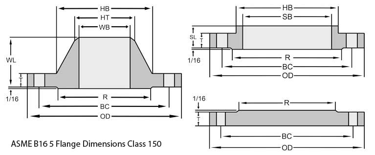
| (NPS) Nominal Pipe Size | (OD) | Minimum Thickness (T) | RF Diameter (R) | Number of Bolt Holes | Holes Diameter | Circle Of Bolt (BC) | So Bore Inside Daimeter (SB) | Diameter Hub Base (HB) | Diameter Hub Top (HT) | SO LTH (SL) | WN LTH (WL) | * WN Bore Inside Daimeter (WB) |
|---|---|---|---|---|---|---|---|---|---|---|---|---|
| 1⁄2 | 4.75 | 0.88 | 1.38 | 4 | 0.88 | 3.25 | 0.88 | 1.50 | 0.84 | 1.25 | 2.38 | * |
| 3⁄4 | 5.12 | 1.00 | 1.69 | 4 | 0.88 | 3.50 | 1.09 | 1.75 | 1.05 | 1.38 | 2.75 | * |
| 1 | 5.88 | 1.12 | 2.00 | 4 | 1.00 | 4.00 | 1.36 | 2.06 | 1.32 | 1.62 | 2.88 | * |
| 11⁄4 | 6.25 | 1.12 | 2.50 | 4 | 1.00 | 4.38 | 1.70 | 2.50 | 1.66 | 1.62 | 2.88 | * |
| 11⁄2 | 7.00 | 1.25 | 2.88 | 4 | 1.12 | 4.88 | 1.95 | 2.75 | 1.90 | 1.75 | 3.25 | * |
| 2 | 8.50 | 1.50 | 3.63 | 8 | 1.00 | 6.50 | 2.44 | 4.12 | 2.38 | 2.25 | 4.00 | * |
| 21⁄2 | 9.62 | 1.62 | 4.13 | 8 | 1.12 | 7.50 | 2.94 | 4.88 | 2.88 | 2.50 | 4.12 | * |
| 3 | 10.50 | 1.88 | 5.00 | 8 | 1.25 | 8.00 | – | 5.25 | 3.50 | – | 4.62 | * |
| 4 | 12.25 | 2.12 | 6.19 | 8 | 1.38 | 9.50 | – | 6.38 | 4.50 | – | 4.88 | * |
| 5 | 14.75 | 2.88 | 7.31 | 8 | 1.63 | 11.50 | – | 7.75 | 5.56 | – | 6.12 | * |
| 6 | 15.50 | 3.25 | 8.50 | 12 | 1.50 | 12.50 | – | 9.00 | 6.63 | – | 6.75 | * |
| 8 | 19.00 | 3.62 | 10.63 | 12 | 1.75 | 15.50 | – | 11.50 | 8.63 | – | 8.38 | * |
| 10 | 23.00 | 4.25 | 12.75 | 12 | 2.00 | 19.00 | – | 14.50 | 10.75 | – | 10.00 | * |
| 12 | 26.50 | 4.88 | 15.00 | 16 | 2.12 | 22.50 | – | 17.75 | 12.75 | – | 11.12 | * |
| 14 | 29.50 | 5.25 | 16.25 | 16 | 2.38 | 25.00 | – | 19.50 | 14.00 | – | 11.75 | * |
| 16 | 32.50 | 5.75 | 18.50 | 16 | 2.63 | 27.75 | – | 21.75 | 16.00 | – | 12.25 | * |
| 18 | 36.00 | 6.38 | 21.00 | 16 | 2.88 | 30.50 | – | 23.50 | 18.00 | – | 12.88 | * |
| 20 | 38.75 | 7.00 | 23.00 | 16 | 3.12 | 32.75 | – | 25.25 | 20.00 | – | 14.00 | * |
| 24 | 46.00 | 8.00 | 27.25 | 16 | 3.63 | 39.00 | – | 30.00 | 24.00 | – | 16.00 | * |
ASTM A105 Class 300 Flange Dimensions
| (NPS) Nominal Pipe Size | (OD) | Minimum Thickness (T) | RF Diameter (R) | Number of Bolt Holes | Holes Diameter | Circle Of Bolt (BC) | SO Bore Inside Daimeter (SB) | WN Bore Inside Daimeter (WB) | Diameter Hub Base (HB) | Diameter Hub Top (HT) | SO LTH (SL) | WN LTH (WL) |
|---|---|---|---|---|---|---|---|---|---|---|---|---|
| 1⁄2 | 3.75 | 0.50 | 1.38 | 4 | 0.63 | 2.62 | 0.88 | 0.62 | 1.50 | 0.84 | 0.81 | 2.00 |
| 3⁄4 | 4.62 | 0.56 | 1.69 | 4 | 0.75 | 3.25 | 1.09 | 0.82 | 1.88 | 1.05 | 0.94 | 2.19 |
| 1 | 4.88 | 0.62 | 2.00 | 4 | 0.75 | 3.50 | 1.36 | 1.05 | 2.12 | 1.32 | 1.00 | 2.38 |
| 11⁄4 | 5.25 | 0.69 | 2.50 | 4 | 0.75 | 3.88 | 1.70 | 1.38 | 2.50 | 1.66 | 1.00 | 2.50 |
| 11⁄2 | 6.12 | 0.75 | 2.88 | 4 | 0.88 | 4.50 | 1.95 | 1.61 | 2.75 | 1.90 | 1.13 | 2.63 |
| 2 | 6.50 | 0.81 | 3.62 | 8 | 0.75 | 5.00 | 2.44 | 2.07 | 3.31 | 2.38 | 1.25 | 2.69 |
| 21⁄2 | 7.50 | 0.94 | 4.12 | 8 | 0.88 | 5.88 | 2.94 | 2.47 | 3.94 | 2.88 | 1.44 | 2.94 |
| 3 | 8.25 | 1.06 | 5.00 | 8 | 0.88 | 6.62 | 3.57 | 3.07 | 4.62 | 3.50 | 1.63 | 3.06 |
| 31⁄2 | 9.00 | 1.12 | 5.50 | 8 | 0.88 | 7.25 | 4.07 | 3.55 | 5.25 | 4.00 | 1.69 | 3.13 |
| 4 | 10.00 | 1.19 | 6.19 | 8 | 0.88 | 7.88 | 4.57 | 4.03 | 5.75 | 4.50 | 1.82 | 3.32 |
| 5 | 11.00 | 1.31 | 7.31 | 8 | 0.88 | 9.25 | 5.66 | 5.05 | 7.00 | 5.56 | 1.94 | 3.82 |
| 6 | 12.50 | 1.38 | 8.50 | 12 | 0.88 | 10.62 | 6.72 | 6.07 | 8.12 | 6.63 | 2.00 | 3.82 |
| 8 | 15.00 | 1.56 | 10.62 | 12 | 1.00 | 13.00 | 8.72 | 7.98 | 10.25 | 8.63 | 2.38 | 4.32 |
| 10 | 17.50 | 1.81 | 12.75 | 16 | 1.12 | 15.25 | 10.88 | 10.02 | 12.62 | 10.75 | 2.56 | 4.56 |
| 12 | 20.50 | 1.94 | 15.00 | 16 | 1.25 | 17.75 | 12.88 | 12.00 | 14.75 | 12.75 | 2.82 | 5.06 |
| 14 | 23.00 | 2.06 | 16.25 | 20 | 1.25 | 20.25 | 14.14 | 13.25 | 16.75 | 14.00 | 2.94 | 5.56 |
| 16 | 25.50 | 2.19 | 18.50 | 20 | 1.38 | 22.50 | 16.16 | 15.25 | 19.00 | 16.00 | 3.19 | 5.69 |
| 18 | 28.00 | 2.31 | 21.00 | 24 | 1.38 | 24.75 | 18.18 | 17.25 | 21.00 | 18.00 | 3.44 | 6.19 |
| 20 | 30.50 | 2.44 | 23.12 | 24 | 1.38 | 27.00 | 20.20 | 19.25 | 23.12 | 20.00 | 3.69 | 6.32 |
| 22 | 33.00 | 2.57 | 25.25 | 24 | 1.63 | 29.25 | 22.22 | 21.25 | 25.25 | 22.00 | 3.93 | 6.43 |
| 24 | 36.00 | 2.69 | 27.62 | 24 | 1.63 | 32.00 | 24.25 | 23.25 | 27.62 | 24.00 | 4.13 | 6.56 |
ASTM A105 Weld Neck Flange Dimensions
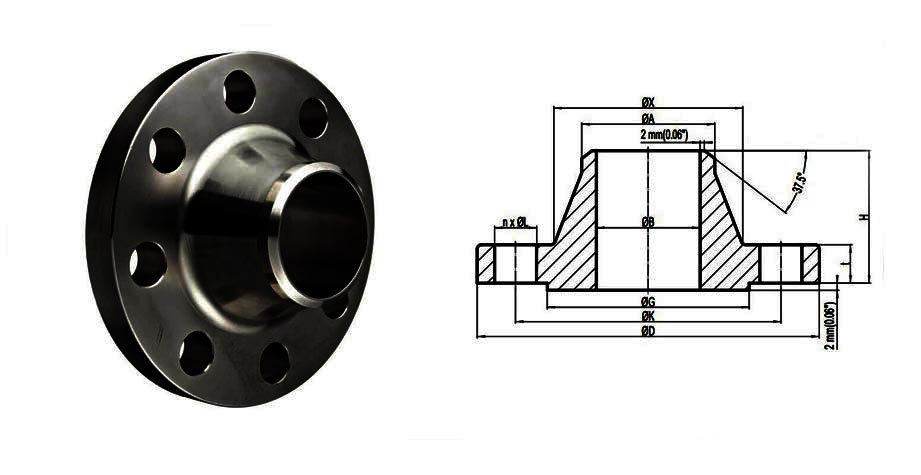
| NPS Size in Inch | NPS Size in mm | (O.D.) Outer Diameter | Thickness Of Flange | Hub Outer Diameter | Weld Neck Outer Diameter | Length Of Welding Neck | Bore | Diameter Of RF | Height Of RF | PCD | Weld Face |
| A | B | C | D | E | F | G | H | I | J | ||
| 1/2 | 15 | 90 | 9.6 | 30 | 21.3 | 46 | - | 34.9 | 2 | 60.3 | 1.6 |
| 3/4 | 20 | 100 | 11.2 | 38 | 26.7 | 51 | 42.9 | 2 | 69.9 | 1.6 | |
| 1 | 25 | 110 | 12.7 | 49 | 33.4 | 54 | 50.8 | 2 | 79.4 | 1.6 | |
| 1 1/4 | 32 | 115 | 14.3 | 59 | 42.2 | 56 | 63.5 | 2 | 88.9 | 1.6 | |
| 1 1/2 | 40 | 125 | 15.9 | 65 | 48.3 | 60 | 73 | 2 | 98.4 | 1.6 | |
| 2 | 50 | 150 | 17.5 | 78 | 60.3 | 62 | 92.1 | 2 | 120.7 | 1.6 | |
| 2 1/2 | 65 | 180 | 20.7 | 90 | 73 | 68 | 104.8 | 2 | 139.7 | 1.6 | |
| 3 | 80 | 190 | 22.3 | 108 | 88.9 | 68 | 127 | 2 | 152.4 | 1.6 | |
| 3 1/2 | 90 | 215 | 22.3 | 122 | 101.6 | 70 | 139.7 | 2 | 177.8 | 1.6 | |
| 4 | 100 | 230 | 22.3 | 135 | 114.3 | 75 | 157.2 | 2 | 190.5 | 1.6 | |
| 5 | 125 | 255 | 22.3 | 164 | 141.3 | 87 | 185.7 | 2 | 215.9 | 1.6 | |
| 6 | 150 | 280 | 23.9 | 192 | 168.3 | 87 | 215.9 | 2 | 241.3 | 1.6 | |
| 8 | 200 | 345 | 27 | 246 | 219.1 | 100 | 269.9 | 2 | 298.5 | 1.6 | |
| 10 | 250 | 405 | 28.6 | 305 | 273 | 100 | 323.8 | 2 | 362 | 1.6 | |
| 12 | 300 | 485 | 30.2 | 365 | 323.8 | 113 | 381 | 2 | 431.8 | 1.6 | |
| 14 | 350 | 535 | 33.4 | 400 | 355.6 | 125 | 412.8 | 2 | 476.3 | 1.6 | |
| 16 | 400 | 595 | 35 | 457 | 406.4 | 125 | 469.9 | 2 | 539.8 | 1.6 | |
| 18 | 450 | 635 | 38.1 | 505 | 457.2 | 138 | 533.4 | 2 | 577.9 | 1.6 | |
| 20 | 500 | 700 | 41.3 | 559 | 508 | 143 | 584.2 | 2 | 635 | 1.6 | |
| 24 | 600 | 815 | 46.1 | 663 | 610 | 151 | 692.2 | 2 | 749.3 | 1.6 |
ASTM A105 Slip On Flange Dimensions
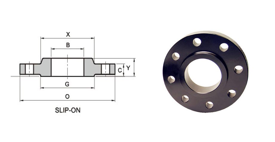
| Normal Pipe Size Of Flanges | (I.D.) Inside Diameter | Outside Daimeter (O.D.) | Circle Of Bolt (BC) | Raised Face (R) |
Raised Face (RF) |
H | Thickness Of Raised Face (T) |
T1 | Thickness Of Flat Face (T2) |
Hole Of Bolt (B) |
Number of Bolt Holes |
|---|---|---|---|---|---|---|---|---|---|---|---|
| 1/2 | 0.88 | 3.50 | 2.38 | 1.38 | .063 | 1.19 | .62 | .38 | .56 | .62 | 4 |
| 3/4 | 1.09 | 3.88 | 2.75 | 1.69 | .063 | 1.50 | .62 | .44 | .56 | .62 | 4 |
| 1 | 1.36 | 4.25 | 3.12 | 2.00 | .063 | 1.94 | .69 | .50 | .63 | .62 | 4 |
| 1-1/4 | 1.70 | 4.62 | 3.50 | 2.50 | .063 | 2.31 | .81 | .56 | .75 | .62 | 4 |
| 1-1/2 | 1.97 | 5.00 | 3.88 | 2.88 | .063 | 2.56 | .88 | .62 | .82 | .62 | 4 |
| 2 | 2.44 | 6.00 | 4.75 | 3.62 | .063 | 3.06 | 1.00 | .69 | .94 | .75 | 4 |
| 2-1/2 | 2.94 | 7.00 | 5.50 | 4.12 | .063 | 3.56 | 1.12 | .82 | 1.06 | .75 | 4 |
| 3 | 3.57 | 7.50 | 6.00 | 5.00 | .063 | 4.25 | 1.19 | .88 | 1.13 | .75 | 4 |
| 3-1/2 | 4.07 | 8.50 | 7.00 | 5.50 | .063 | 4.81 | 1.25 | .88 | 1.19 | .75 | 8 |
| 4 | 4.57 | 9.00 | 7.50 | 6.19 | .063 | 5.31 | 1.31 | .88 | 1.25 | .75 | 8 |
| 5 | 5.66 | 10.00 | 8.50 | 7.31 | .063 | 6.44 | 1.44 | .88 | 1.38 | .88 | 8 |
| 6 | 6.72 | 11.00 | 9.50 | 8.50 | .063 | 7.56 | 1.56 | .94 | 1.50 | .88 | 8 |
| 8 | 8.72 | 13.50 | 11.75 | 10.62 | .063 | 9.69 | 1.75 | 1.06 | 1.69 | .88 | 8 |
| 10 | 10.88 | 16.00 | 14.25 | 12.75 | .063 | 12.00 | 1.94 | 1.13 | 1.88 | 1.00 | 12 |
| 12 | 12.88 | 19.00 | 17.00 | 15.00 | .063 | 14.38 | 2.19 | 1.19 | 2.13 | 1.00 | 12 |
| 14 | 14.14 | 21.00 | 18.75 | 16.25 | .063 | 15.75 | 2.25 | 1.32 | 2.19 | 1.12 | 12 |
| 16 | 16.16 | 23.50 | 21.25 | 18.50 | .063 | 18.00 | 2.50 | 1.38 | 2.44 | 1.12 | 16 |
| 18 | 18.18 | 25.00 | 22.75 | 21.00 | .063 | 19.88 | 2.69 | 1.50 | 2.63 | 1.25 | 16 |
| 20 | 20.20 | 27.50 | 25.00 | 23.00 | .063 | 22.00 | 2.88 | 1.63 | 2.83 | 1.25 | 20 |
| 22 | 22.22 | 29.50 | 27.25 | 25.25 | .063 | 24.25 | 3.13 | 1.75 | 3.07 | 1.38 | 20 |
| 24 | 24.25 | 32.00 | 29.50 | 27.25 | .063 | 26.12 | 3.25 | 1.82 | 3.19 | 1.38 | 20 |
SA105 Blind Flange Dimensions
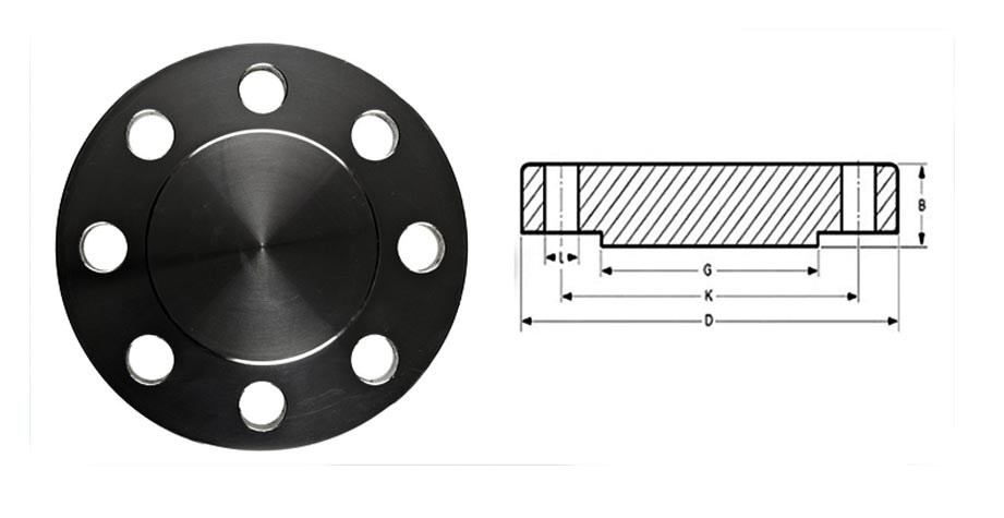
| NPS (Normal Pipe Sizes) | "A" (O.D.) Outside Daimeter |
"B" (Thickness) |
"C" (RF Daimeter) |
"D" (B.C.D.) |
# Bolt Holes |
Daimeter of Bolt Holes |
Approx. Weight In Kg |
|---|---|---|---|---|---|---|---|
| 1/2" | 3-1/2 | 7/16 | 1-3/8 | 2-3/8 | 4 | 5/8 | 2 |
| 3/4" | 3-7/8 | 1/2 | 1-11/16 | 2-3/4 | 4 | 5/8 | 2 |
| 1" | 4-1/4 | 9/16 | 2 | 3-1/8 | 4 | 5/8 | 2 |
| 1-1/4" | 4-5/8 | 5/8 | 2-1/2 | 3-1/2 | 4 | 5/8 | 3 |
| 1-1/2" | 5 | 11/16 | 2-7/8 | 3-7/8 | 4 | 5/8 | 3 |
| 2" | 6 | 3/4 | 3-5/8 | 4-3/4 | 4 | 3/4 | 4 |
| 2-1/2" | 7 | 7/8 | 4-1/8 | 5-1/2 | 4 | 3/4 | 7 |
| 3" | 7-1/2 | 15/16 | 5 | 6 | 4 | 3/4 | 9 |
| 3-1/2" | 8-1/2 | 15/16 | 5-1/2 | 7 | 8 | 3/4 | 13 |
| 4" | 9 | 15/16 | 6-3/16 | 7-1/2 | 8 | 3/4 | 17 |
| 5" | 10 | 15/16 | 7-5/16 | 8-1/2 | 8 | 7/8 | 20 |
| 6" | 11 | 1 | 8-1/2 | 9-1/2 | 8 | 7/8 | 27 |
| 8" | 13-1/2 | 1-1/8 | 10-5/8 | 11-3/4 | 8 | 7/8 | 47 |
| 10" | 16 | 1-3/16 | 12-3/4 | 14-1/4 | 12 | 1 | 67 |
| 12" | 19 | 1-1/4 | 15 | 17 | 12 | 1 | 123 |
| 14" | 21 | 1-3/8 | 16-1/4 | 18-3/4 | 12 | 1-1/8 | 139 |
| 16" | 23-1/2 | 1-7/16 | 18-1/2 | 21-1/4 | 16 | 1-1/8 | 187 |
| 18" | 25 | 1-9/16 | 21 | 22-3/4 | 16 | 1-1/4 | 217 |
| 20" | 27-1/2 | 1-11/16 | 23 | 25 | 20 | 1-1/4 | 283 |
| 24" | 32 | 1-7/8 | 27-1/4 | 29-1/2 | 20 | 1-3/8 | 415 |
ASTM A105 Heat Treatment
Heat treatment is not a mandatory requirement of ANSI A105 Flanges piping components. However, there are some exceptions: ASME B16.5 flanges 150 Class, Class 400, Class 900, Class 1500, Class 2500; Flanges of special design where the design pressure at the design temperature exceeds the pressure-temperature ratings of Class 300; Flanges of special design where the design pressure or temperature are not known; Forged fittings or valve parts which are over 4″ and Class 300 RF.
What Is The Difference Between A105 And A105N
ASTM A105 Material by default is not normalization heat treated. A105 Flanges are called the Ansi A105n Flanges where the n stands for normalization heat treatment. The heat treatment makes the A105 much harder and stronger.
A105N Flange can be used to fit pipes of two different diameters. One end of the flange corresponds to the diameter of one pipe and the other end of the reducing flange corresponds to the diameter of the other pipe in the connection.
What Is The Difference Between A105 And A234
A105 Flange cannot be used in extreme conditions because of the carbon steel material. They can stand up to certain levels but not overtake the high chromium molybdenum alloy counterparts of them.
A234 WPB are made up of wrought carbon steel that they are very strong and can be applied in high strength requirements. The A234 are heat treated and then allowed to cool rapidly.
Special Price For Type Of ASTM A105 Carbon Steel Flanges
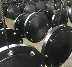
CS Forged Flanges
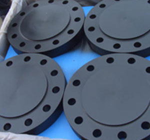
ASME SA105 Carbon Steel Raised Face Flanges
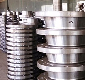
Carbon Steel ASTM a105n Male and Female Flanges
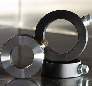
ASTM a105n Bleed Ring
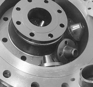
Carbon Steel ASTM A105 Plate Flanges
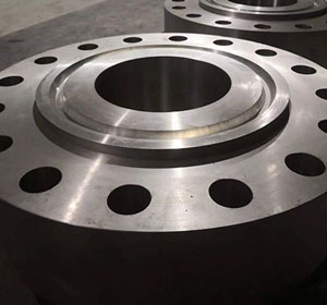
ASTM A105 Ring Type Joint Flanges
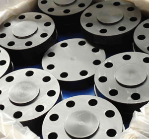
A105 Carbon Steel Tongue & Groove Flanges
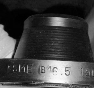
ASTM A105 Reducing Flanges
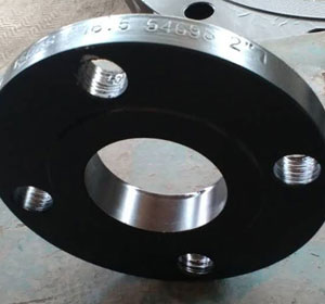
ASTM a105 Carbon Steel Slip On Flanges
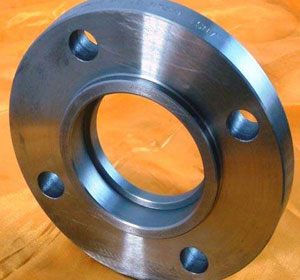
ASTM A105 Socket Weld Flanges
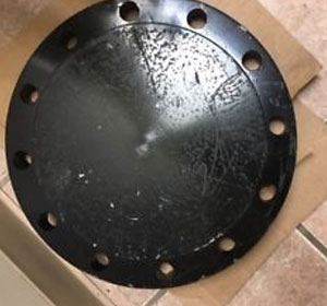
ASTM a105 Carbon Steel Blind Flanges
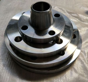
Carbon Steel sa105 Weld Neck Flanges
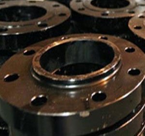
Carbon Steel ASME sa105 Threaded/ Screwed Flanges
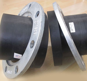
ASTM A105n Lap Joint Flanges
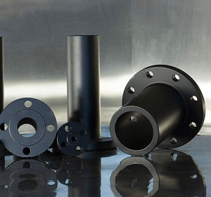
Carbon Steel ASTM A105 Long Weld Neck Flanges
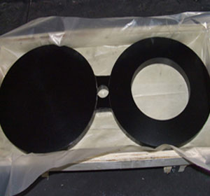
Carbon Steel ASTM A105N Spectacle Blind Flanges
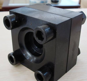
Carbon Steel Square Flange
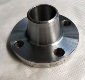
ASTM A105n High hub Blind Flange
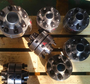
Carbon Steel ASTM A105 Orifice Flanges
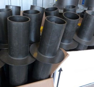
Carbon Steel ASTM A105N Puddle Flange
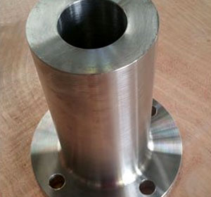
Carbon Steel ASME SA105 Expander Flange
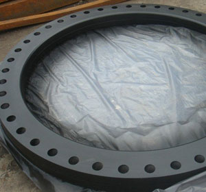
Carbon Steel ASTM A105 Flat Flange
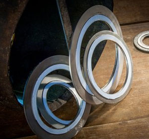
Carbon Steel ASTM A105 Flange Gasket

Carbon Steel ASTM A105N Hydraulic Sae Flanges
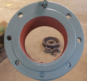
ASTM A105n Flange Adapter
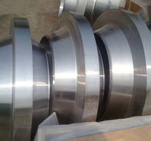
Carbon Steel ASTM A105N Anchor Flange
We Have Recently Delivered ASTM A105 Carbon Steel Flanges To The Following Countries:
| 3 Inch, SCH 120, RF, BS EN 10204, Carbon Steel Flanges | Philippines, Canada, Malaysia, Singapore |
| Class 600, 6 Inch, RF, ASME B16.5, astm a105 flange | Romania, Europe, Japan, Malaysia |
| Class 300, 6 Inch, BS 10, Sch 80, A105 Pipe Flange | China, Colombia, Sweden, Malaysia |
| 10 Inch, SCH 20, LTCS, Class 2500, carbon steel slip-on flanges | Europe, UAE, United Kingdom -UK, Malaysia |
| 4 Inch Class 150, RF, BS 3293, carbon steel blind flanges | Kuwait, Brazil, Saudi Arabia (KSA), South Africa |
| Class 150, 6 Inch, BS 3293, Raised Face, cs flanges | Bahrain, South Africa, Singapore |
| 3 Inch, 300#, SCH 40, B16.5, FF, black steel flanges | Australia, Philippines, UK, Nigeria |
| ASTM A105N, 11 Inch, FF, 150 LB, Carbon Steel A105 Blind Flange | Hong Kong, Oman, UAE, Malaysia |
| 12 Inch, Class 150, SCH 60, Carbon Steel Pipe Flanges | Iran, Chile, Singapore, Italy |
| Class 600, RF, 30 Inch, SCH 40, Carbon Steel Forged Flanges | Norway, Turkey, United Arab Emirates (UAE), Malaysia |
| 16 Inch, 150LB, RF, A105N Flange | Belgium, Philippines, Dammam -KSA, Indonesia. |
| 20 Inch, Class 300, SCH STD, B16.5, Carbon Steel Weld Flanges | France, Qatar, Thailand, Europe |
| 2 Inch, SCH 160, B16.5, CL1500, Blacl Steel SORF Flanges | Germany, Czechia, Malaysia, Thailand |
| 8 Inch, RF, Class 150, Dual Rated, astm a105n material | Bangladesh, Finland, USA, Malaysia |
| 16 Inch, 600#, API 590, Flate Face (FF), Carbon Steel Pipe Flange | Dubai, Netherlands, Russia, Malaysia |
| ASTM A105N, 8 Inch, Class 300, SCh 60, A105 Wnrf Flanges | Mexico, Egypt, UK, Spain |
| 14 Inch, Class 900, ANSI B16.5, FF, CS Flanges | Poland, Canada, UK, Ellington -United States |
