ASME B16.5 Flange
PDO Approved ASME B16.5 Pipe Flanges Manufacturer In India And ASA B16.5 Flange Design Specifications.
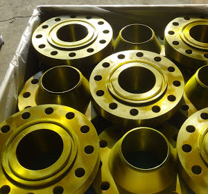
Buttweld Fittings
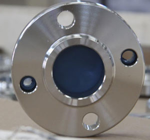
ASME B16.5 Pipe Flange
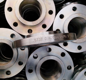
ANSI b16 5 Standard Flange
What Does ASME B16 5 Mean?
ASME B16.5 are components that are used to fit together two pipes or a pipe with other components in a system. They could either be connected by bolt and nut or by welding together. ANSI B16.5 Flanges belong to the standard B16.5. industrial flange have a category that can hold the classes 150 through 2500 and their diameter ranges from ¼ inches to 24 inches. ASA B16.5 Class 600 Flanges belong in the same category but with a higher maximum pressure capacity. industrial pipe flange is a specification of forged flanges. ASME B16.5 pipe flange are preferred by our customers for their durability, corrosion resistance and excellent performance. Their applications and use cases vary. Class 600 Flanges have higher maximum pressure so that they can be applied in heavy duty systems.
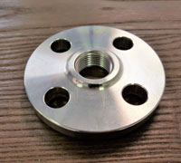
Flange Manufacturer In India
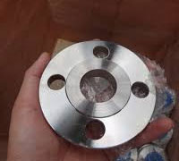
ASME B16 5 Flange Dimensions Class 150
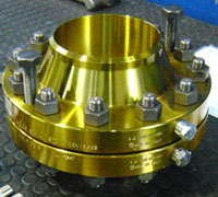
Flanges Used In Oil And Gas Industry
Table of contents
- What Is ANSI Class 150 Flange?
- ASME B16.5 Material Specification
- Standard Pipe Flange Dimensions In Mm
- ANSI B16.5 Class 150 Flange Dimensions
- Class 300 Flange Dimensions
- ANSI B16.5 Class 400 Flange Dimensions
- ANSI 600 Flange Dimensions In MM
- ANSI B16.5 Class 900 Flange Dimensions
- ASME B16.5 Class 1500 Flange Dimensions
- ASME B16.5 Class 2500 Flange Dimensions
- Pipe Flange Size Chart
- ASME B16.5 Pressure Temperature Ratings
- ASTM Material Grades As Per ANSI B16.5
- ASME B16.5 Flange Weight Chart
- Calculation Flange Hole Marking Formula
- Industrial Flange Chemical Composition
- ASME Flange Bolt Length Chart
- ANSI Flange Bore Diameter
- ASME B16.5 Tolerances
- Type Of ANSI B16.5 According To ASME-ANSI-DIN-2627-EN-1092
- Different Types Contact Faces For B16.5 Flanges
- Flange Thickness Calculation For Pressure Vessel
- Industrial Pipe Flange Bolt Chart
- ASME B16.5 Flange Gasket Dimensions
- Types Of Flanges Used In Oil And Gas Industry
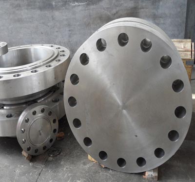
What Is ANSI Class 150 Flange?
ANSI B16.5 Class 150 Flange is a pressure class that can handle a maximum pressure of 285psi. Flange sizes from 26 inches and above are governed by ASME B16.5 standards. Class 150 Flanges are mutually the same except is heavier and costly with less bolt holes. 150 LB Flanges are commonly used in applications where the piping system is less than 14 inches in diameter.
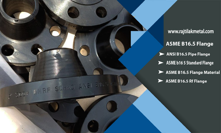
Check ANSI B16.5 Class 150/ 300/ 400/ 600/ 900/ 1500/ 2500 Forged Flanges Dimensions In MM.
As the leading ANSI B16.5 Flanges manufacturer in India, we also supply ASME B16.5 Flange which has high corrosion resistance against most oxidizing and reducing media. flange material are used in steel pipe lines where strength is the primary concern. DIN86029 PN10 Flanges can withstand pressure levels up to 10 bars. It is a rating system with Pression Number (PN) which indicates in bars how much pressure the flange can withstand. We also supply Non Standard Flanges and flanges used in oil and gas industry and many other varieties of stainless steel flanges.
ASME B16.5 Material Specification
| Material Specification Of: | ASME B16.5 Flange |
|---|---|
| ASME B16.5 Standard Cover : | pressure ratings & temperature ratings, materials, marking, dimensions, weight, tolerances, testing |
| Contact Faces For ANSI B16.5 | RTJ (Ring Type Joint), FF (Flat Face), RF (Raised Face), T/G (Tongue And Groove ), M/F (Male And Female) |
| Size Chart | Normal Pipe Size 1/2 to NPS 24" |
| Materials | Stainless Steel (Grade 304/L, 316/L), Carbon Steel (ASTM A105 And ASTM A350), Alloy Steel (ASTM A182), Mild Steel, Duplex Steel, Pressure Vessel Steel, Titanium, Super Duplex Steel, Nickel Alloy, Monel, Inconel, Hastelloy, Copper Nickel, Cast Iron, Wrought Iron. |
| Thickness Of ASME B16.5 | Normal Pipe Size ≤ 18 |
| Bore Diameter Of ANSI B16.5 | Normal Pipe ≤ 10 |
| Flanges Standards | EN 1092-1, JIS, ASME B16.5, ASME B16.47 type A, UNI, DIN |
| ASME B16.5 Pressure Rating | Class 150 To Class 2500 |
| High Temperature Of ASME B16.5 | Above 200°C (400°F) For Class 150 Or Above 400°C (750°F) |
| Low Temperature Of ANSI B16.5 | Above -29 Degree C (−20°F) |
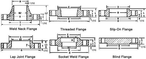
| Common Types Of ASME B16.5 | Slip On (SORF), Weld Neck (WNRF), Blind (BLRF), Lap Joint (Loose), Threaded (NPT), Socket-Weld (SWRF) |
| ASME B16.5 Marking Standard | Name of Manufacturer Schedule Type of Flange Facing Nominal Pipe Size Pressure Class ASME B16 Designation |
| ASME B16.5 Bolt Type | high strength bolts medium strength bolts low strength bolts |
| European Standard Flanges | JIS B2220 Flanges (5k to 30k) and KS1503 flanges |
| Russian-Standard Flanges | GOST 12820 / 12821-80, DIN, UNI, EN 1092-1 |
| South African Standard Flanges | SANSflanges And SABS flanges |
| Surface Finish Of ASME B16.5 | smooth, concentric serrated, stock |
| ANSI B16.5 Flanges Gaskets Types | Full Face Gasket Flat Ring Gasket Metallic Ring Gakset |
| Advantages Of Pipe Flange | Used to Connect Pipe System Easy Repair Pipe System Assembled Without Welding |
Standard Pipe Flange Dimensions In Mm
ANSI B16.5 Class 150 Flange Dimensions
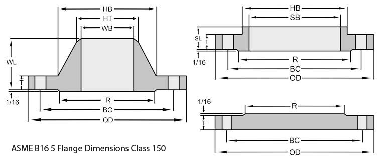
| (NPS) Nominal Pipe Size | (OD) | Minimum Thickness (T) | RF Diameter (R) | Number of Bolt Holes | Holes Diameter | Circle Of Bolt (BC) | So Bore Inside Daimeter (SB) | Diameter Hub Base (HB) | Diameter Hub Top (HT) | SO LTH (SL) | WN LTH (WL) | * WN Bore Inside Daimeter (WB) |
|---|---|---|---|---|---|---|---|---|---|---|---|---|
| 1⁄2 | 4.75 | 0.88 | 1.38 | 4 | 0.88 | 3.25 | 0.88 | 1.50 | 0.84 | 1.25 | 2.38 | * |
| 3⁄4 | 5.12 | 1.00 | 1.69 | 4 | 0.88 | 3.50 | 1.09 | 1.75 | 1.05 | 1.38 | 2.75 | * |
| 1 | 5.88 | 1.12 | 2.00 | 4 | 1.00 | 4.00 | 1.36 | 2.06 | 1.32 | 1.62 | 2.88 | * |
| 11⁄4 | 6.25 | 1.12 | 2.50 | 4 | 1.00 | 4.38 | 1.70 | 2.50 | 1.66 | 1.62 | 2.88 | * |
| 11⁄2 | 7.00 | 1.25 | 2.88 | 4 | 1.12 | 4.88 | 1.95 | 2.75 | 1.90 | 1.75 | 3.25 | * |
| 2 | 8.50 | 1.50 | 3.63 | 8 | 1.00 | 6.50 | 2.44 | 4.12 | 2.38 | 2.25 | 4.00 | * |
| 21⁄2 | 9.62 | 1.62 | 4.13 | 8 | 1.12 | 7.50 | 2.94 | 4.88 | 2.88 | 2.50 | 4.12 | * |
| 3 | 10.50 | 1.88 | 5.00 | 8 | 1.25 | 8.00 | – | 5.25 | 3.50 | – | 4.62 | * |
| 4 | 12.25 | 2.12 | 6.19 | 8 | 1.38 | 9.50 | – | 6.38 | 4.50 | – | 4.88 | * |
| 5 | 14.75 | 2.88 | 7.31 | 8 | 1.63 | 11.50 | – | 7.75 | 5.56 | – | 6.12 | * |
| 6 | 15.50 | 3.25 | 8.50 | 12 | 1.50 | 12.50 | – | 9.00 | 6.63 | – | 6.75 | * |
| 8 | 19.00 | 3.62 | 10.63 | 12 | 1.75 | 15.50 | – | 11.50 | 8.63 | – | 8.38 | * |
| 10 | 23.00 | 4.25 | 12.75 | 12 | 2.00 | 19.00 | – | 14.50 | 10.75 | – | 10.00 | * |
| 12 | 26.50 | 4.88 | 15.00 | 16 | 2.12 | 22.50 | – | 17.75 | 12.75 | – | 11.12 | * |
| 14 | 29.50 | 5.25 | 16.25 | 16 | 2.38 | 25.00 | – | 19.50 | 14.00 | – | 11.75 | * |
| 16 | 32.50 | 5.75 | 18.50 | 16 | 2.63 | 27.75 | – | 21.75 | 16.00 | – | 12.25 | * |
| 18 | 36.00 | 6.38 | 21.00 | 16 | 2.88 | 30.50 | – | 23.50 | 18.00 | – | 12.88 | * |
| 20 | 38.75 | 7.00 | 23.00 | 16 | 3.12 | 32.75 | – | 25.25 | 20.00 | – | 14.00 | * |
| 24 | 46.00 | 8.00 | 27.25 | 16 | 3.63 | 39.00 | – | 30.00 | 24.00 | – | 16.00 | * |
Class 300 Flange Dimensions
| (NPS) Nominal Pipe Size | (OD) | Minimum Thickness (T) | RF Diameter (R) | Number of Bolt Holes | Holes Diameter | Circle Of Bolt (BC) | So Bore Inside Daimeter (SB) | Diameter Hub Base (HB) | Diameter Hub Top (HT) | SO LTH (SL) | WN LTH (WL) | * WN Bore Inside Daimeter (WB) |
|---|---|---|---|---|---|---|---|---|---|---|---|---|
| 1⁄2 | 4.75 | 0.88 | 1.38 | 4 | 0.88 | 3.25 | 0.88 | 1.50 | 0.84 | 1.25 | 2.38 | * |
| 3⁄4 | 5.12 | 1.00 | 1.69 | 4 | 0.88 | 3.50 | 1.09 | 1.75 | 1.05 | 1.38 | 2.75 | * |
| 1 | 5.88 | 1.12 | 2.00 | 4 | 1.00 | 4.00 | 1.36 | 2.06 | 1.32 | 1.62 | 2.88 | * |
| 11⁄4 | 6.25 | 1.12 | 2.50 | 4 | 1.00 | 4.38 | 1.70 | 2.50 | 1.66 | 1.62 | 2.88 | * |
| 11⁄2 | 7.00 | 1.25 | 2.88 | 4 | 1.12 | 4.88 | 1.95 | 2.75 | 1.90 | 1.75 | 3.25 | * |
| 2 | 8.50 | 1.50 | 3.63 | 8 | 1.00 | 6.50 | 2.44 | 4.12 | 2.38 | 2.25 | 4.00 | * |
| 21⁄2 | 9.62 | 1.62 | 4.13 | 8 | 1.12 | 7.50 | 2.94 | 4.88 | 2.88 | 2.50 | 4.12 | * |
| 3 | 10.50 | 1.88 | 5.00 | 8 | 1.25 | 8.00 | – | 5.25 | 3.50 | – | 4.62 | * |
| 4 | 12.25 | 2.12 | 6.19 | 8 | 1.38 | 9.50 | – | 6.38 | 4.50 | – | 4.88 | * |
| 5 | 14.75 | 2.88 | 7.31 | 8 | 1.63 | 11.50 | – | 7.75 | 5.56 | – | 6.12 | * |
| 6 | 15.50 | 3.25 | 8.50 | 12 | 1.50 | 12.50 | – | 9.00 | 6.63 | – | 6.75 | * |
| 8 | 19.00 | 3.62 | 10.63 | 12 | 1.75 | 15.50 | – | 11.50 | 8.63 | – | 8.38 | * |
| 10 | 23.00 | 4.25 | 12.75 | 12 | 2.00 | 19.00 | – | 14.50 | 10.75 | – | 10.00 | * |
| 12 | 26.50 | 4.88 | 15.00 | 16 | 2.12 | 22.50 | – | 17.75 | 12.75 | – | 11.12 | * |
| 14 | 29.50 | 5.25 | 16.25 | 16 | 2.38 | 25.00 | – | 19.50 | 14.00 | – | 11.75 | * |
| 16 | 32.50 | 5.75 | 18.50 | 16 | 2.63 | 27.75 | – | 21.75 | 16.00 | – | 12.25 | * |
| 18 | 36.00 | 6.38 | 21.00 | 16 | 2.88 | 30.50 | – | 23.50 | 18.00 | – | 12.88 | * |
| 20 | 38.75 | 7.00 | 23.00 | 16 | 3.12 | 32.75 | – | 25.25 | 20.00 | – | 14.00 | * |
| 24 | 46.00 | 8.00 | 27.25 | 16 | 3.63 | 39.00 | – | 30.00 | 24.00 | – | 16.00 | * |
ANSI B16.5 Class 400 Flange Dimensions
| (NPS) Nominal Pipe Size | (OD) | Minimum Thickness (T) | RF Diameter (R) | Number of Bolt Holes | Holes Diameter | Circle Of Bolt (BC) | SO Bore Inside Daimeter (SB) | Diameter Hub Base (HB) | Diameter Hub Top (HT) | SO LTH (SL) | WN LTH (WL) | * WN Bore Inside Daimeter (WB) |
|---|---|---|---|---|---|---|---|---|---|---|---|---|
| 1⁄2 | 3.75 | 0.56 | 1.38 | 4 | 0.63 | 2.62 | 0.88 | 1.5 | 0.84 | 0.88 | 2.06 | * |
| 3⁄4 | 4.62 | 0.62 | 1.69 | 4 | 0.75 | 3.25 | 1.09 | 1.88 | 1.05 | 1.00 | 2.25 | * |
| 1 | 4.88 | 0.69 | 2.00 | 4 | 0.75 | 3.50 | 1.36 | 2.12 | 1.32 | 1.06 | 2.44 | * |
| 11⁄4 | 5.25 | 0.81 | 2.50 | 4 | 0.75 | 3.88 | 1.70 | 2.50 | 1.66 | 1.12 | 2.62 | * |
| 11⁄2 | 6.12 | 0.88 | 2.88 | 4 | 0.88 | 4.50 | 1.95 | 2.75 | 1.90 | 1.25 | 2.75 | * |
| 2 | 6.50 | 1.00 | 3.62 | 8 | 0.75 | 5.00 | 2.44 | 3.31 | 2.38 | 1.44 | 2.88 | * |
| 21⁄2 | 7.50 | 1.12 | 4.12 | 8 | 0.88 | 5.88 | 2.94 | 3.94 | 2.88 | 1.62 | 3.12 | * |
| 3 | 8.25 | 1.25 | 5.00 | 8 | 0.88 | 6.62 | 3.57 | 4.62 | 3.50 | 1.81 | 3.25 | * |
| 31⁄2 | 9.00 | 1.38 | 5.50 | 8 | 1.00 | 7.25 | 4.07 | 5.25 | 4.00 | 1.94 | 3.38 | * |
| 4 | 10.00 | 1.38 | 6.19 | 8 | 1.00 | 7.88 | 4.57 | 5.75 | 4.50 | 2.00 | 3.50 | * |
| 5 | 11.00 | 1.50 | 7.31 | 8 | 1.00 | 9.25 | 5.66 | 7.00 | 5.56 | 2.12 | 4.00 | * |
| 6 | 12.50 | 1.62 | 8.50 | 12 | 1.00 | 10.62 | 6.72 | 8.12 | 6.63 | 2.25 | 4.06 | * |
| 8 | 15.00 | 1.88 | 10.62 | 12 | 1.12 | 13.00 | 8.72 | 10.25 | 8.63 | 2.69 | 4.62 | * |
| 10 | 17.50 | 2.12 | 12.75 | 16 | 1.25 | 15.25 | 10.88 | 12.62 | 10.75 | 2.88 | 4.88 | * |
| 12 | 20.50 | 2.25 | 15.00 | 16 | 1.38 | 17.75 | 12.88 | 14.75 | 12.75 | 3.12 | 5.38 | * |
| 14 | 23.00 | 2.38 | 16.25 | 20 | 1.38 | 20.25 | 14.14 | 16.75 | 14.00 | 3.31 | 5.88 | * |
| 16 | 25.50 | 2.50 | 18.50 | 20 | 1.50 | 22.50 | 16.16 | 19.00 | 16.00 | 3.69 | 6.00 | * |
| 18 | 28.00 | 2.62 | 21.00 | 24 | 1.50 | 24.75 | 18.18 | 21.00 | 18.00 | 3.88 | 6.50 | * |
| 20 | 30.50 | 2.75 | 23.12 | 24 | 1.62 | 27.00 | 20.20 | 23.12 | 20.00 | 4.00 | 6.62 | * |
| 22 | 33.00 | 2.88 | 25.25 | 24 | 1.75 | 29.25 | 22.22 | 25.25 | 22.00 | 4.25 | 6.75 | * |
| 24 | 36.00 | 3.00 | 27.25 | 24 | 1.88 | 32.00 | 24.25 | 27.62 | 24.00 | 4.50 | 6.88 | * |
ANSI 600 Flange Dimensions In MM
| (NPS) Nominal Pipe Size | (OD) | Minimum Thickness (T) | RF Diameter (R) | Number of Bolt Holes | Holes Diameter | Circle Of Bolt (BC) | SO Bore Inside Daimeter (SB) | Diameter Hub Base (HB) | Diameter Hub Top (HT) | SO LTH (SL) | WN LTH (WL) | * WN Bore Inside Daimeter (WB) |
|---|---|---|---|---|---|---|---|---|---|---|---|---|
| 1⁄2 | 3.75 | 0.56 | 1.38 | 4 | 0.63 | 2.62 | 0.88 | 1.50 | 0.84 | 0.88 | 2.06 | * |
| 3⁄4 | 4.62 | 0.62 | 1.69 | 4 | 0.75 | 3.25 | 1.09 | 1.88 | 1.05 | 1.00 | 2.25 | * |
| 1 | 4.88 | 0.69 | 2.00 | 4 | 0.75 | 3.50 | 1.36 | 2.12 | 1.32 | 1.06 | 2.44 | * |
| 11⁄4 | 5.25 | 0.81 | 2.50 | 4 | 0.75 | 3.88 | 1.70 | 2.50 | 1.66 | 1.12 | 2.62 | * |
| 11⁄2 | 6.12 | 0.88 | 2.88 | 4 | 0.88 | 4.50 | 1.95 | 2.75 | 1.90 | 1.25 | 2.75 | * |
| 2 | 6.50 | 1.00 | 3.62 | 8 | 0.75 | 5.00 | 2.44 | 3.31 | 2.38 | 1.44 | 2.88 | * |
| 21⁄2 | 7.50 | 1.12 | 4.12 | 8 | 0.88 | 5.88 | 2.94 | 3.94 | 2.88 | 1.62 | 3.12 | * |
| 3 | 8.25 | 1.25 | 5.00 | 8 | 0.88 | 6.62 | 3.57 | 4.62 | 3.50 | 1.81 | 3.25 | * |
| 31⁄2 | 9.00 | 1.38 | 5.50 | 8 | 1.00 | 7.25 | 4.07 | 5.25 | 4.00 | 1.94 | 3.38 | * |
| 4 | 10.75 | 1.50 | 6.19 | 8 | 1.00 | 8.50 | 4.57 | 6.00 | 4.50 | 2.12 | 4.00 | * |
| 5 | 13.00 | 1.75 | 7.31 | 8 | 1.12 | 10.50 | 5.66 | 7.44 | 5.56 | 2.38 | 4.50 | * |
| 6 | 14.00 | 1.88 | 8.50 | 12 | 1.12 | 11.50 | 6.72 | 8.75 | 6.63 | 2.62 | 4.62 | * |
| 8 | 16.50 | 2.19 | 10.62 | 12 | 1.25 | 13.75 | 8.72 | 10.75 | 8.63 | 3.00 | 5.25 | * |
| 10 | 20.00 | 2.50 | 12.75 | 16 | 1.38 | 17.00 | 10.88 | 13.50 | 10.75 | 3.38 | 6.00 | * |
| 12 | 22.00 | 2.62 | 15.00 | 20 | 1.38 | 19.25 | 12.88 | 15.75 | 12.75 | 3.62 | 6.12 | * |
| 14 | 23.75 | 2.75 | 16.25 | 20 | 1.50 | 20.75 | 14.14 | 17.00 | 14.00 | 3.69 | 6.50 | * |
| 16 | 27.00 | 3.00 | 18.50 | 20 | 1.63 | 23.75 | 16.16 | 19.50 | 16.00 | 4.19 | 7.00 | * |
| 18 | 29.25 | 3.25 | 21.00 | 20 | 1.75 | 25.75 | 18.18 | 21.50 | 18.00 | 4.62 | 7.25 | * |
| 20 | 32.00 | 3.50 | 23.00 | 24 | 1.75 | 28.50 | 20.20 | 24.00 | 20.00 | 5.00 | 7.50 | * |
| 22 | 34.25 | 3.75 | 25.25 | 24 | 1.88 | 30.63 | 22.22 | 26.25 | 22.00 | 5.25 | 7.75 | * |
| 24 | 37.00 | 4.00 | 27.25 | 24 | 2.00 | 33.00 | 24.25 | 28.25 | 24.00 | 5.50 | 8.00 | * |
ANSI B16.5 Class 900 Flange Dimensions
| (NPS) Nominal Pipe Size | (OD) | Minimum Thickness (T) | RF Diameter (R) | Number of Bolt Holes | Holes Diameter | Circle Of Bolt (BC) | SO Bore ID (SB) | * WN Bore ID (WB) | Diameter Hub Base (HB) | Diameter Hub Top (HT) | SO LTH (SL) | WN LTH (WL) |
|---|---|---|---|---|---|---|---|---|---|---|---|---|
| 3 | 9.50 | 1.50 | 5.00 | 8 | 1.00 | 7.50 | 3.57 | * | 5.00 | 3.50 | 2.12 | 4.00 |
| 4 | 11.50 | 1.75 | 6.19 | 8 | 1.25 | 9.25 | 4.57 | * | 6.25 | 4.50 | 2.75 | 4.50 |
| 5 | 13.75 | 2.00 | 7.31 | 8 | 1.38 | 11.00 | 5.66 | * | 7.50 | 5.56 | 3.12 | 5.00 |
| 6 | 15.00 | 2.19 | 8.50 | 12 | 1.25 | 12.50 | 6.72 | * | 9.25 | 6.63 | 3.38 | 5.50 |
| 8 | 18.50 | 2.50 | 10.63 | 12 | 1.50 | 15.50 | 8.72 | * | 11.75 | 8.63 | 4.00 | 6.38 |
| 10 | 21.50 | 2.75 | 12.75 | 16 | 1.50 | 18.50 | 10.88 | * | 14.50 | 10.75 | 4.25 | 7.25 |
| 12 | 24.00 | 3.12 | 15.00 | 20 | 1.50 | 21.00 | 12.88 | * | 16.50 | 12.75 | 4.63 | 7.88 |
| 14 | 25.25 | 3.38 | 16.25 | 20 | 1.63 | 22.00 | 14.14 | * | 17.75 | 14.00 | 5.12 | 8.38 |
| 16 | 27.75 | 3.50 | 18.50 | 20 | 1.75 | 24.25 | 16.16 | * | 20.00 | 16.00 | 5.25 | 8.50 |
| 18 | 31.00 | 4.00 | 21.00 | 20 | 2.00 | 27.00 | 18.18 | * | 22.25 | 18.00 | 6.00 | 9.00 |
| 20 | 33.75 | 4.25 | 23.00 | 20 | 2.13 | 29.50 | 20.20 | * | 24.50 | 20.00 | 6.25 | 9.75 |
| 24 | 41.00 | 5.50 | 27.25 | 20 | 2.63 | 35.50 | 24.25 | * | 29.50 | 24.00 | 8.00 | 11.50 |
ASME B16.5 Class 1500 Flange Dimensions
| (NPS) Nominal Pipe Size | (OD) | Minimum Thickness (T) | RF Diameter (R) | Number of Bolt Holes | Holes Diameter | Circle Of Bolt (BC) | So Bore Inside Daimeter (SB) | Diameter Hub Base (HB) | Diameter Hub Top (HT) | SO LTH (SL) | WN LTH (WL) | * WN Bore Inside Daimeter (WB) |
|---|---|---|---|---|---|---|---|---|---|---|---|---|
| 1⁄2 | 4.75 | 0.88 | 1.38 | 4 | 0.88 | 3.25 | 0.88 | 1.50 | 0.84 | 1.25 | 2.38 | * |
| 3⁄4 | 5.12 | 1.00 | 1.69 | 4 | 0.88 | 3.50 | 1.09 | 1.75 | 1.05 | 1.38 | 2.75 | * |
| 1 | 5.88 | 1.12 | 2.00 | 4 | 1.00 | 4.00 | 1.36 | 2.06 | 1.32 | 1.62 | 2.88 | * |
| 11⁄4 | 6.25 | 1.12 | 2.50 | 4 | 1.00 | 4.38 | 1.70 | 2.50 | 1.66 | 1.62 | 2.88 | * |
| 11⁄2 | 7.00 | 1.25 | 2.88 | 4 | 1.12 | 4.88 | 1.95 | 2.75 | 1.90 | 1.75 | 3.25 | * |
| 2 | 8.50 | 1.50 | 3.63 | 8 | 1.00 | 6.50 | 2.44 | 4.12 | 2.38 | 2.25 | 4.00 | * |
| 21⁄2 | 9.62 | 1.62 | 4.13 | 8 | 1.12 | 7.50 | 2.94 | 4.88 | 2.88 | 2.50 | 4.12 | * |
| 3 | 10.50 | 1.88 | 5.00 | 8 | 1.25 | 8.00 | – | 5.25 | 3.50 | – | 4.62 | * |
| 4 | 12.25 | 2.12 | 6.19 | 8 | 1.38 | 9.50 | – | 6.38 | 4.50 | – | 4.88 | * |
| 5 | 14.75 | 2.88 | 7.31 | 8 | 1.63 | 11.50 | – | 7.75 | 5.56 | – | 6.12 | * |
| 6 | 15.50 | 3.25 | 8.50 | 12 | 1.50 | 12.50 | – | 9.00 | 6.63 | – | 6.75 | * |
| 8 | 19.00 | 3.62 | 10.63 | 12 | 1.75 | 15.50 | – | 11.50 | 8.63 | – | 8.38 | * |
| 10 | 23.00 | 4.25 | 12.75 | 12 | 2.00 | 19.00 | – | 14.50 | 10.75 | – | 10.00 | * |
| 12 | 26.50 | 4.88 | 15.00 | 16 | 2.12 | 22.50 | – | 17.75 | 12.75 | – | 11.12 | * |
| 14 | 29.50 | 5.25 | 16.25 | 16 | 2.38 | 25.00 | – | 19.50 | 14.00 | – | 11.75 | * |
| 16 | 32.50 | 5.75 | 18.50 | 16 | 2.63 | 27.75 | – | 21.75 | 16.00 | – | 12.25 | * |
| 18 | 36.00 | 6.38 | 21.00 | 16 | 2.88 | 30.50 | – | 23.50 | 18.00 | – | 12.88 | * |
| 20 | 38.75 | 7.00 | 23.00 | 16 | 3.12 | 32.75 | – | 25.25 | 20.00 | – | 14.00 | * |
| 24 | 46.00 | 8.00 | 27.25 | 16 | 3.63 | 39.00 | – | 30.00 | 24.00 | – | 16.00 | * |
ASME B16.5 Class 2500 Flange Dimensions
| (NPS) Nominal Pipe Size | (OD) | Minimum Thickness (T) | RF Diameter (R) | Number of Bolt Holes | Holes Diameter | Circle Of Bolt (BC) | Diameter Hub Base (HB) | Diameter Hub Top (HT) | SO LTH (SL) | WN LTH (WL) | * WN Bore ID (WB) |
|---|---|---|---|---|---|---|---|---|---|---|---|
| 1⁄2 | 5.25 | 1.19 | 1.38 | 4 | 0.88 | 3.50 | 1.69 | 0.84 | 1.56 | 2.88 | * |
| 3⁄4 | 5.50 | 1.25 | 1.69 | 4 | 0.88 | 3.75 | 2.00 | 1.05 | 1.69 | 3.12 | * |
| 1 | 6.25 | 1.38 | 2.00 | 4 | 1.00 | 4.25 | 2.25 | 1.32 | 1.88 | 3.50 | * |
| 11⁄4 | 7.25 | 1.50 | 2.50 | 4 | 1.12 | 5.13 | 2.88 | 1.66 | 2.06 | 3.75 | * |
| 11⁄2 | 8.00 | 1.75 | 2.88 | 4 | 1.25 | 5.75 | 3.12 | 1.90 | 2.38 | 4.38 | * |
| 2 | 9.25 | 2.00 | 3.63 | 8 | 1.12 | 6.75 | 3.75 | 2.38 | 2.75 | 5.00 | * |
| 21⁄2 | 10.50 | 2.25 | 4.13 | 8 | 1.25 | 7.75 | 4.50 | 2.88 | 3.12 | 5.62 | * |
| 3 | 12.00 | 2.62 | 5.00 | 8 | 1.38 | 9.00 | 5.25 | 3.50 | – | 6.62 | * |
| 4 | 14.00 | 3.00 | 6.19 | 8 | 1.63 | 10.75 | 6.50 | 4.50 | – | 7.50 | * |
| 5 | 16.50 | 3.62 | 7.31 | 8 | 1.88 | 12.75 | 8.00 | 5.56 | – | 9.00 | * |
| 6 | 19.00 | 4.25 | 8.50 | 8 | 2.12 | 14.50 | 9.25 | 6.63 | – | 10.75 | * |
| 8 | 21.75 | 5.00 | 10.63 | 12 | 2.12 | 17.25 | 12.00 | 8.63 | – | 12.50 | * |
| 10 | 26.50 | 6.50 | 12.75 | 12 | 2.63 | 21.25 | 14.75 | 10.75 | – | 16.50 | * |
| 12 | 30.00 | 7.25 | 15.00 | 12 | 2.88 | 24.38 | 17.38 | 12.75 | – | 18.25 | * |
Refer Industrial Pipe Flanges Weight Chart According to ASME B16.5 And 150# Flange Bolt Chart.
Pipe Flange Size Chart
| DN In inches | Dimension | ASME B16.5 Dimensional Sizes 1/2 inches to 2 1/2 inches | ||||||||||||||
|---|---|---|---|---|---|---|---|---|---|---|---|---|---|---|---|---|
| 125# 150# | 300# | 400# | 600# | 900# | 1500# | 2500# | ||||||||||
| inches | millimeter | inches | millimeter | inches | millimeter | inches | millimeter | inches | millimeter | inches | millimeter | inches | millimeter | |||
| 1/2 | A | 3 1/2 | 88.9 | 3 3/4 | 95.2 | 3 3/4 | 95.2 | 3 3/4 | 95.2 | 4 3/4 | 121 | 4 3/4 | 121 | 5 1/4 | 133.4 | |
| b | 7/16 | 11.1 | 9/16 | 14.3 | 9/16 | 14.3 | 9/16 | 14.3 | 7/8 | 22.2 | 7/8 | 22.2 | 1 3/16 | 30.2 | ||
| D2 | 1 3/8 | 34.9 | 1 3/8 | 34.9 | 1 3/8 | 34.9 | 1 3/8 | 34.9 | 1 3/8 | 34.9 | 1 3/8 | 34.9 | 1 3/8 | 34.9 | ||
| D1 | 2 3/8 | 60.3 | 2 5/8 | 66.7 | 2 5/8 | 66.7 | 2 5/8 | 66.7 | 3 1/4 | 82.6 | 3 1/4 | 82.6 | 3 1/2 | 88.9 | ||
| n | 4 | 4 | 4 | 4 | 4 | 4 | 4 | 4 | 4 | 4 | 4 | - | 4 | 44 | ||
| d | 5/8 | 15.9 | 5/8 | 15.9 | 5/8 | 15.9 | 5/8 | 15.9 | 7/8 | 22.2 | 7/8 | 22.2 | 7/8 | 22.2 | ||
| 3/4 | A | 3 7/8 | 98.4 | 4 5/8 | 117.5 | 4 5/8 | 117.5 | 4 5/8 | 117.5 | 5 1/8 | 130 | 5 1/8 | 130 | 5 1/2 | 139.7 | |
| b | 1/2 | 12.7 | 5/8 | 15.9 | 5/8 | 15.9 | 5/8 | 15.9 | 1 | 25.4 | 1 | 25.4 | 1 1/4 | 31.8 | ||
| D2 | 1 11/16 | 42.9 | 1 11/16 | 42.9 | 1 11/16 | 42.9 | 1 11/16 | 42.9 | 1 11/16 | 42.9 | 1 11/16 | 42.9 | 1 11/16 | 42.9 | ||
| D1 | 2 3/4 | 69.8 | 3 1/4 | 82.5 | 3 1/4 | 82.5 | 3 1/4 | 82.5 | 3 1/2 | 88.9 | 3 1/2 | 88.9 | 3 3/4 | 95.2 | ||
| n | 4 | 4 | 4 | 4 | 4 | 4 | 4 | 4 | 4 | 4 | 4 | - | 4 | 44 | ||
| d | 5/8 | 15.9 | 3/4 | 19 | 3/4 | 19 | 3/4 | 19 | 7/8 | 22.2 | 7/8 | 22.2 | 7/8 | 22.2 | ||
| 1 | A | 4 1/4 | 108 | 4 7/8 | 123.8 | 4 7/8 | 123.8 | 4 7/8 | 123.8 | 5 7/8 | 149.2 | 5 7/8 | 149.2 | 6 1/4 | 159 | |
| b | 9/16 | 14.3 | 11/16 | 17.5 | 11/16 | 17.5 | 11/16 | 17.5 | 1 1/8 | 28.6 | 1 1/8 | 28.6 | 1 3/8 | 34.9 | ||
| D2 | 2 | 50.8 | 2 | 50.8 | 2 | 50.8 | 2 | 50.8 | 2 | 50.8 | 2 | 50.8 | 2 | 50.8 | ||
| D1 | 3 1/8 | 79.4 | 3 1/2 | 88.9 | 3 1/2 | 88.9 | 3 1/2 | 88.9 | 4 | 102 | 4 | 102 | 4 1/4 | 108 | ||
| n | 4 | 4 | 4 | 4 | 4 | 4 | 4 | 4 | 4 | 4 | 4 | 4 | 4 | 4 | ||
| d | 5/8 | 15.9 | 3/4 | 19 | 3/4 | 19 | 3/4 | 19 | 1 | 25.4 | 1 | 25.4 | 1 | 25.4 | ||
| 1 1/4 | A | 4 5/8 | 117.5 | 5 1/4 | 133.4 | 5 1/4 | 133.4 | 5 1/4 | 133.4 | 6 1/4 | 159 | 6 1/4 | 159 | 7 1/4 | 184.2 | |
| b | 5/8 | 15.9 | 3/4 | 19 | 13/16 | 20.6 | 13/16 | 20.6 | 1 1/8 | 28.6 | 1 1/8 | 28.6 | 1 1/2 | 38.1 | ||
| D2 | 2 1/2 | 63.5 | 2 1/2 | 63.5 | 2 1/2 | 63.5 | 2 1/2 | 63.5 | 2 1/2 | 63.5 | 2 1/2 | 63.5 | 2 1/2 | 63.5 | ||
| D1 | 3 1/2 | 88.9 | 3 7/8 | 98.4 | 3 7/8 | 98.4 | 3 7/8 | 98.4 | 4 3/8 | 111 | 4 3/8 | 111 | 5 1/8 | 130 | ||
| n | 4 | 4 | 4 | 4 | 4 | 4 | 4 | 4 | 4 | 4 | 4 | 4 | 4 | 4 | ||
| d | 5/8 | 15.9 | 3/4 | 19 | 3/4 | 19 | 3/4 | 19 | 1 | 25.4 | 1 | 25.4 | 1 1/8 | 28.6 | ||
| 1 1/2 | A | 5 | 127 | 6 1/8 | 155.6 | 6 1/8 | 155.6 | 6 1/8 | 155.6 | 7 | 177.8 | 7 | 177.8 | 8 | 203 | |
| b | 11/16 | 17.5 | 13/16 | 20.6 | 7/8 | 22.2 | 7/8 | 22.2 | 1 1/4 | 31.8 | 1 1/4 | 31.8 | 1 3/4 | 44.5 | ||
| D2 | 2 7/8 | 73 98 | 2 7/8 | 73 | 2 7/8 | 73 | 2 7/8 | 73 | 2 7/8 | 73 | 2 7/8 | 73 | 2 7/8 | 73 | ||
| D1 | 3 7/8 | 4 | 4 1/2 | 114 | 4 1/2 | 114 | 4 1/2 | 114 | 4 7/8 | 124 | 4 7/8 | 124 | 5 3/4 | 146 | ||
| n | 4 | 4 | 4 | 4 | 4 | 4 | 4 | 4 | 4 | 4 | 4 | 4 | 4 | 4 | ||
| d | 5/8 | . 15.9 | 7/8 | 22.2 | 7/8 | 22.2 | 7/8 | 22.2 | 1 1/8 | 28.6 | 1 1/8 | 28.6 | 1 1/4 | 31.8 | ||
| 2 | A | 6 | 152.4 | 6 1/2 | 165.1 | 6 1/2 | 165.1 | 6 1/2 | 165.1 | 8 1/2 | 215.9 | 8 1/2 | 215.9 | 9 1/4 | 234.9 | |
| b | 3/4 | 19 | 7/8 | 22.2 | 1 | 25.4 | 1 | 25.4 | 1 1/2 | 38.1 | 1 1/2 | 38.1 | 2 | 50.8 | ||
| D2 | 3 5/8 | 92.1 | 3 5/8 | 92.1 | 3 5/8 | 92.1 | 3 5/8 | 92.1 | 3 5/8 | 92.1 | 3 5/8 | 92.1 | 3 5/8 | 92.1 | ||
| D1 | 4 3/4 | 121 | 5 | 127 | 5 | 127 | 5 | 127 | 6 1/2 | 165.1 | 6 1/2 | 165.1 | 6 3/4 | 171 | ||
| n | 4 | 4 | 8 | 8 | 8 | 8 | 8 | 8 | 8 | 8 | 8 | 8 | 8 | 8 | ||
| d | 3/4 | 19 | 3/4 | 19 | 3/4 | 19 | 3/4 | 19 | 1 | 25.4 | 1 | 25.4 | 1 1/8 | 28.6 | ||
| 2 1/2 | A | 7 | 177.8 | 7 1/2 | 190.5 | 7 1/2 | 190.5 | 7 1/2 | 190.5 | 9 5/8 | 244 | 9 5/8 | 244 | 10 1/2 | 266.7 | |
| b | 7/8 | 22.2 | 1 | 25.4 | 1 1/8 | 28.6 | 1 1/8 | 28.6 | 1 5/8 | 41.3 | 1 5/8 | 41.3 | 2 1/4 | 57.2 | ||
| D2 | 4 1/8 | 104.8 | 4 1/8 | 104.8 | 4 1/8 | 104.8 | 4 1/8 | 104.8 | 4 1/8 | 105 | 4 1/8 | 105 | 4 1/8 | 105 | ||
| D1 | 5 1/2 | 139.7 | 5 7/8 | 149.2 | 5 7/8 | 149.2 | 5 7/8 | 149.2 | 7 1/2 | 190.5 | 7 1/2 | 190.5 | 7 3/4 | 197 | ||
| n | 4 | 4 | 8 | 8 | 8 | 8 | 8 | 8 | 8 | 8 | 8 | 8 | 8 | 8 | ||
| d | 3/4 | 19 | 7/8 | 22.2 | 7/8 | 22.2 | 7/8 | 22.2 | 1 1/8 | 28.6 | 1 1/8 | 28.6 | 1 1/4 | 31.8 | ||
View ASME B16.5 Flange Pressure Rating And Grooved Flange Thickness Calculation For Pressure Vessel.
| DN In inches | Dimension | ASME B16.5 Dimensional Sizes 1/2 inches to 2 1/2 inches | ||||||||||||||
|---|---|---|---|---|---|---|---|---|---|---|---|---|---|---|---|---|
| 125# 150# | 300# | 400# | 600# | 900# | 1500# | 2500# | ||||||||||
| inches | millimeter | inches | millimeter | inches | millimeter | inches | millimeter | inches | millimeter | inches | millimeter | inches | millimeter | |||
| 1/2 | A | 3 1/2 | 88.9 | 3 3/4 | 95.2 | 3 3/4 | 95.2 | 3 3/4 | 95.2 | 4 3/4 | 121 | 4 3/4 | 121 | 5 1/4 | 133.4 | |
| b | 7/16 | 11.1 | 9/16 | 14.3 | 9/16 | 14.3 | 9/16 | 14.3 | 7/8 | 22.2 | 7/8 | 22.2 | 1 3/16 | 30.2 | ||
| D2 | 1 3/8 | 34.9 | 1 3/8 | 34.9 | 1 3/8 | 34.9 | 1 3/8 | 34.9 | 1 3/8 | 34.9 | 1 3/8 | 34.9 | 1 3/8 | 34.9 | ||
| D1 | 2 3/8 | 60.3 | 2 5/8 | 66.7 | 2 5/8 | 66.7 | 2 5/8 | 66.7 | 3 1/4 | 82.6 | 3 1/4 | 82.6 | 3 1/2 | 88.9 | ||
| n | 4 | 4 | 4 | 4 | 4 | 4 | 4 | 4 | 4 | 4 | 4 | - | 4 | 44 | ||
| d | 5/8 | 15.9 | 5/8 | 15.9 | 5/8 | 15.9 | 5/8 | 15.9 | 7/8 | 22.2 | 7/8 | 22.2 | 7/8 | 22.2 | ||
| 3/4 | A | 3 7/8 | 98.4 | 4 5/8 | 117.5 | 4 5/8 | 117.5 | 4 5/8 | 117.5 | 5 1/8 | 130 | 5 1/8 | 130 | 5 1/2 | 139.7 | |
| b | 1/2 | 12.7 | 5/8 | 15.9 | 5/8 | 15.9 | 5/8 | 15.9 | 1 | 25.4 | 1 | 25.4 | 1 1/4 | 31.8 | ||
| D2 | 1 11/16 | 42.9 | 1 11/16 | 42.9 | 1 11/16 | 42.9 | 1 11/16 | 42.9 | 1 11/16 | 42.9 | 1 11/16 | 42.9 | 1 11/16 | 42.9 | ||
| D1 | 2 3/4 | 69.8 | 3 1/4 | 82.5 | 3 1/4 | 82.5 | 3 1/4 | 82.5 | 3 1/2 | 88.9 | 3 1/2 | 88.9 | 3 3/4 | 95.2 | ||
| n | 4 | 4 | 4 | 4 | 4 | 4 | 4 | 4 | 4 | 4 | 4 | - | 4 | 44 | ||
| d | 5/8 | 15.9 | 3/4 | 19 | 3/4 | 19 | 3/4 | 19 | 7/8 | 22.2 | 7/8 | 22.2 | 7/8 | 22.2 | ||
| 1 | A | 4 1/4 | 108 | 4 7/8 | 123.8 | 4 7/8 | 123.8 | 4 7/8 | 123.8 | 5 7/8 | 149.2 | 5 7/8 | 149.2 | 6 1/4 | 159 | |
| b | 9/16 | 14.3 | 11/16 | 17.5 | 11/16 | 17.5 | 11/16 | 17.5 | 1 1/8 | 28.6 | 1 1/8 | 28.6 | 1 3/8 | 34.9 | ||
| D2 | 2 | 50.8 | 2 | 50.8 | 2 | 50.8 | 2 | 50.8 | 2 | 50.8 | 2 | 50.8 | 2 | 50.8 | ||
| D1 | 3 1/8 | 79.4 | 3 1/2 | 88.9 | 3 1/2 | 88.9 | 3 1/2 | 88.9 | 4 | 102 | 4 | 102 | 4 1/4 | 108 | ||
| n | 4 | 4 | 4 | 4 | 4 | 4 | 4 | 4 | 4 | 4 | 4 | 4 | 4 | 4 | ||
| d | 5/8 | 15.9 | 3/4 | 19 | 3/4 | 19 | 3/4 | 19 | 1 | 25.4 | 1 | 25.4 | 1 | 25.4 | ||
| 1 1/4 | A | 4 5/8 | 117.5 | 5 1/4 | 133.4 | 5 1/4 | 133.4 | 5 1/4 | 133.4 | 6 1/4 | 159 | 6 1/4 | 159 | 7 1/4 | 184.2 | |
| b | 5/8 | 15.9 | 3/4 | 19 | 13/16 | 20.6 | 13/16 | 20.6 | 1 1/8 | 28.6 | 1 1/8 | 28.6 | 1 1/2 | 38.1 | ||
| D2 | 2 1/2 | 63.5 | 2 1/2 | 63.5 | 2 1/2 | 63.5 | 2 1/2 | 63.5 | 2 1/2 | 63.5 | 2 1/2 | 63.5 | 2 1/2 | 63.5 | ||
| D1 | 3 1/2 | 88.9 | 3 7/8 | 98.4 | 3 7/8 | 98.4 | 3 7/8 | 98.4 | 4 3/8 | 111 | 4 3/8 | 111 | 5 1/8 | 130 | ||
| n | 4 | 4 | 4 | 4 | 4 | 4 | 4 | 4 | 4 | 4 | 4 | 4 | 4 | 4 | ||
| d | 5/8 | 15.9 | 3/4 | 19 | 3/4 | 19 | 3/4 | 19 | 1 | 25.4 | 1 | 25.4 | 1 1/8 | 28.6 | ||
| 1 1/2 | A | 5 | 127 | 6 1/8 | 155.6 | 6 1/8 | 155.6 | 6 1/8 | 155.6 | 7 | 177.8 | 7 | 177.8 | 8 | 203 | |
| b | 11/16 | 17.5 | 13/16 | 20.6 | 7/8 | 22.2 | 7/8 | 22.2 | 1 1/4 | 31.8 | 1 1/4 | 31.8 | 1 3/4 | 44.5 | ||
| D2 | 2 7/8 | 73 98 | 2 7/8 | 73 | 2 7/8 | 73 | 2 7/8 | 73 | 2 7/8 | 73 | 2 7/8 | 73 | 2 7/8 | 73 | ||
| D1 | 3 7/8 | 4 | 4 1/2 | 114 | 4 1/2 | 114 | 4 1/2 | 114 | 4 7/8 | 124 | 4 7/8 | 124 | 5 3/4 | 146 | ||
| n | 4 | 4 | 4 | 4 | 4 | 4 | 4 | 4 | 4 | 4 | 4 | 4 | 4 | 4 | ||
| d | 5/8 | . 15.9 | 7/8 | 22.2 | 7/8 | 22.2 | 7/8 | 22.2 | 1 1/8 | 28.6 | 1 1/8 | 28.6 | 1 1/4 | 31.8 | ||
| 2 | A | 6 | 152.4 | 6 1/2 | 165.1 | 6 1/2 | 165.1 | 6 1/2 | 165.1 | 8 1/2 | 215.9 | 8 1/2 | 215.9 | 9 1/4 | 234.9 | |
| b | 3/4 | 19 | 7/8 | 22.2 | 1 | 25.4 | 1 | 25.4 | 1 1/2 | 38.1 | 1 1/2 | 38.1 | 2 | 50.8 | ||
| D2 | 3 5/8 | 92.1 | 3 5/8 | 92.1 | 3 5/8 | 92.1 | 3 5/8 | 92.1 | 3 5/8 | 92.1 | 3 5/8 | 92.1 | 3 5/8 | 92.1 | ||
| D1 | 4 3/4 | 121 | 5 | 127 | 5 | 127 | 5 | 127 | 6 1/2 | 165.1 | 6 1/2 | 165.1 | 6 3/4 | 171 | ||
| n | 4 | 4 | 8 | 8 | 8 | 8 | 8 | 8 | 8 | 8 | 8 | 8 | 8 | 8 | ||
| d | 3/4 | 19 | 3/4 | 19 | 3/4 | 19 | 3/4 | 19 | 1 | 25.4 | 1 | 25.4 | 1 1/8 | 28.6 | ||
| 2 1/2 | A | 7 | 177.8 | 7 1/2 | 190.5 | 7 1/2 | 190.5 | 7 1/2 | 190.5 | 9 5/8 | 244 | 9 5/8 | 244 | 10 1/2 | 266.7 | |
| b | 7/8 | 22.2 | 1 | 25.4 | 1 1/8 | 28.6 | 1 1/8 | 28.6 | 1 5/8 | 41.3 | 1 5/8 | 41.3 | 2 1/4 | 57.2 | ||
| D2 | 4 1/8 | 104.8 | 4 1/8 | 104.8 | 4 1/8 | 104.8 | 4 1/8 | 104.8 | 4 1/8 | 105 | 4 1/8 | 105 | 4 1/8 | 105 | ||
| D1 | 5 1/2 | 139.7 | 5 7/8 | 149.2 | 5 7/8 | 149.2 | 5 7/8 | 149.2 | 7 1/2 | 190.5 | 7 1/2 | 190.5 | 7 3/4 | 197 | ||
| n | 4 | 4 | 8 | 8 | 8 | 8 | 8 | 8 | 8 | 8 | 8 | 8 | 8 | 8 | ||
| d | 3/4 | 19 | 7/8 | 22.2 | 7/8 | 22.2 | 7/8 | 22.2 | 1 1/8 | 28.6 | 1 1/8 | 28.6 | 1 1/4 | 31.8 | ||
ASME B16.5 Pressure Temperature Ratings
| ASME B16.5 Pressure Pressure | |||||||
|---|---|---|---|---|---|---|---|
| Temperature (°C) | Class | ||||||
| Class 150 | Class 300 | Class 400 | Class 600 | Class 900 | Class 1500 | Class 2500 | |
| -29 - 38 | 19.8 | 51.7 | 68.9 | 103.4 | 155 | 259 | 431 |
| 50 | 19.5 | 51.7 | 68.9 | 103.4 | 155 | 259 | 431 |
| 100 | 17.7 | 51.5 | 68.7 | 103.0 | 155 | 258 | 429 |
| 150 | 15.8 | 50.2 | 66.8 | 100.3 | 151 | 251 | 418 |
| 200 | 13.8 | 48.6 | 64.8 | 97.2 | 146 | 243 | 405 |
| 250 | 12.1 | 46.3 | 61.7 | 92.7 | 139 | 232 | 386 |
| 300 | 10.2 | 42.9 | 57.0 | 85.7 | 129 | 214 | 357 |
| 325 | 9.3 | 41.4 | 55.0 | 82.6 | 124 | 207 | 344 |
| 350 | 8.4 | 40.0 | 53.4 | 80.0 | 120 | 200 | 334 |
| 375 | 7.4 | 37.8 | 50.4 | 75.7 | 114 | 189 | 315 |
| 400 | 6.5 | 34.7 | 46.3 | 69.4 | 104 | 174 | 290 |
| 425 | 5.5 | 28.8 | 38.4 | 57.5 | 86.3 | 144 | 240 |
| 450 | 4.6 | 23.0 | 30.7 | 46.0 | 69.0 | 115 | 192 |
| 475 | 3.7 | 17.1 | 22.8 | 34.2 | 51.3 | 85.4 | 142 |
| 500 | 2.8 | 11.6 | 15.4 | 23.2 | 34.7 | 57.9 | 96.5 |
| 538 | 1.4 | 5.9 | 7.9 | 11.8 | 17.7 | 29.5 | 49.2 |
ASTM Material Grades As Per ANSI B16.5
| Material | Pipes | Fittings | Flanges | Valves | Bolt & Nut |
| Carbon Steel | A106 gr A | A234 gr WPA | A105 | A216 gr WCB | A193 Grades B7 A194 Grades 2H |
| A106 Grades B | A234 gr WPB | A105 | A216 Grades WCB | ||
| A106 gr C | A234 Grades WPC | A105 | A216 Grades WCB | ||
| Carbon Steel Alloy High-Temp |
A335 gr P1 | A234 gr WP1 | A182 gr F1 | A217 gr WC1 | A193 Grades B7 A194 Grades 2H |
| A335 gr P11 | A234 Grades WP11 | A182 gr F11 | A217 Grades WC6 | ||
| A335 Grades P12 | A234 gr WP12 | A182 Grades F12 | A217 gr WC6 | ||
| A335 gr P22 | A234 Grades WP22 | A182 Grades F22 | A217 gr WC9 | ||
| A335 gr P5 | A234 Grades WP5 | A182 Grades F5 | A217 gr C5 | ||
| A335 gr P9 | A234 Grades WP9 | A182 gr F9 | A217 Grades C12 | ||
| Carbon Steel Alloy Low-Temp |
A333 gr 6 | A420 gr WPL6 | A350 gr LF2 | A352 Grades LCB | A320 gr L7 A194 Grades 7 |
| A333 gr 3 | A420 Grade WPL3 | A350 Grade LF3 | A352 gr LC3 | ||
| Austenitic Stainless Steel |
A312 gr TP304 | A403 Grade WP304 | A182 gr F304 | A182 Grade F304 | A193 Grade B8 A194 Grade 8 |
| A312 Grade TP316 | A403 Grade WP316 | A182 Grade F316 | A182 Gr F316 | ||
| A312 Gr TP321 | A403 Gr WP321 | A182 Gr F321 | A182 Gr F321 | ||
| A312 Gr TP347 | A403 Gr WP347 | A182 Gr F347 | A182 Gr F347 | ||
ASME B16.5 Flange Weight Chart
| Nominal Pipe Sizes (NPS) | Slip On (SORF) | Threaded (NPT) | Socket Weld (SWRF) | Lap Joint (Loose) | Blind (BLRF) | Weld Neck (WRNR) |
|---|---|---|---|---|---|---|
| ½ | 1 | 1 | 2 | 1 | 2 | 2 |
| ¾ | 2 | 2 | 2 | 2 | 2 | 2 |
| 1 | 2 | 2 | 2 | 2 | 2 | 3 |
| 1¼ | 3 | 3 | 3 | 3 | 3 | 3 |
| 1½ | 3 | 3 | 3 | 3 | 4 | 4 |
| 2 | 5 | 5 | 5 | 5 | 5 | 6 |
| 2½ | 8 | 8 | 8 | 8 | 7 | 10 |
| 3 | 9 | 9 | 9 | 9 | 9 | 11.5 |
| 3½ | 11 | 12 | 11 | 11 | 13 | 12 |
| 4 | 13 | 13 | 13 | 13 | 17 | 16.5 |
| 5 | 15 | 15 | 15 | 15 | 20 | 21 |
| 6 | 19 | 19 | 19 | 19 | 27 | 26 |
| 8 | 30 | 30 | 30 | 30 | 47 | 42 |
| 10 | 43 | 43 | 43 | 43 | 70 | 54 |
| 12 | 64 | 64 | 64 | 64 | 123 | 88 |
| 14 | 90 | 90 | 90 | 105 | 140 | 114 |
| 16 | 106 | 98 | 98 | 140 | 180 | 140 |
| 18 | 130 | 130 | 130 | 160 | 220 | 165 |
| 20 | 165 | 165 | 165 | 195 | 285 | 197 |
| 22 | 185 | 185 | 185 | 245 | 355 | 225 |
| 24 | 220 | 220 | 220 | 275 | 430 | 268 |
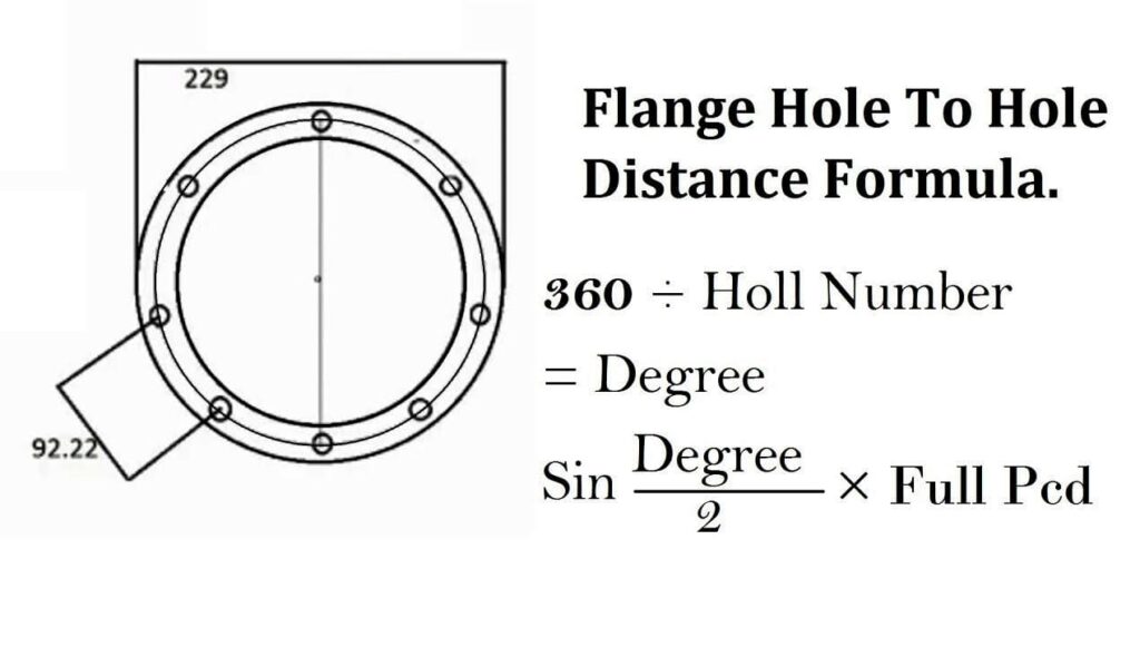
Calculation Flange Hole Marking Formula
Industrial Flange Chemical Composition
|
C |
Mn |
P |
S |
Si |
Cu |
Ni |
Cr |
Mo |
V |
|
0.35 |
0.60-1.05 |
0.035 |
0.04 |
0.10-0.35 |
0.4 |
0.4 |
0.3 |
0.12 |
0.08 |
|
maxi. |
– |
maxi. |
maxi. |
– |
maximum (1) |
maximum (1) |
maximum (1-2) |
maximum (1-2) |
maximum |
ASME Flange Bolt Length Chart
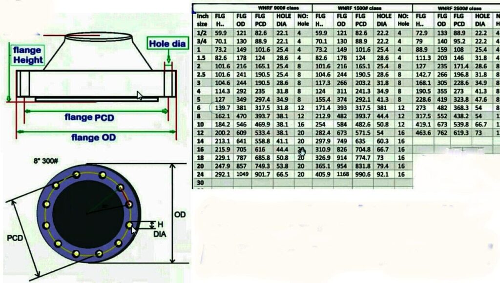
- Flange H. = Flanges Hight
- Flange O.D. = Outside Diameters
- Flange PCD = Pitch Circum Face Diameter Hole To Hole Dimensions
- Flange Hole Dia = Bolting Hole Sizes
- Flange No. = Number Of Bolting Holes
ANSI Flange Bore Diameter
Lap Joint and SORF Flange Bores
| Size | Tolerance |
|---|---|
| Normal Pipe Size ≤ 10 | +1.0, -0.0 millimeter (+0.03,-0.0 in.) |
| Normal Pipe Size ≥ 12 | +1.5, -0.0 millimeter (+0.06,-0.0 in.) |
Counter Bores, NPT Flanges
| Normal Pipe Size | Tolerance |
|---|---|
| Normal Pipe Size (NPS) ≤ 10 | +1.0, -0.0 millimeter (+0.03,-0.0 inches) |
| Normal Pipe Size (NPS) ≥ 12 | +1.5, -0.0 millimeter (+0.06,-0.0 inches) |
Counter Bores, Welding Flanges
| Size | Tolerance |
|---|---|
| 1/2 ≤ Normal Pipe Size (NPS) ≤ 3 | ±0.25 millimeter (±0.010 inches) |
Check NPT Flange Size Chart And Tolerance Chart Of PN16 Flanges, Gasket Flange Supplier In Mumbai, India.
ASME B16.5 Tolerances
| ASME B16.5 | Tolerance | |
|---|---|---|
| A | Outside Diameter (O.D.) |
|
| D | Inside Diameter |
|
| B | Diameter of contact face |
|
| J | Diameter of hub at base |
|
| H | Diameter of hub at point of welding |
|
| P | Drilling |
|
| Eccentricity of bolt circle with respect to facing |
|
|
| C | Thickness |
|
| K | Length of hub |
|
Type Of ANSI B16.5 According To ASME-ANSI-DIN-2627-EN-1092
| Types | EN standard | DIN standard | Pressure | Gr. |
|---|---|---|---|---|
| Weld-on Collars | EN1092-1/32 | DIN 2641 | 2642 | 2655 | 2656 | PN6, Pn10, 16, 25, 40, 63, 100, 160, 250, 320, Pn400 |
S235JR, P250GH / C 22.8, P245GH, P265GH, P280GH, P355NH, 16Mo3, 13CrMo4-5, P355QH1 / W/TStE 355, 1.4301, 1.4307, 1.4541, 1.4401, 1.4404, 1.4571, 1.4410 (Superduplex), 1.4462 (Duplex) |
| Flat (FF) Flange | EN1092-1/01 | DIN 2573 | 2576 | PN6, PN10, PN16, PN25, PN40, PN63, PN100, PN160, PN250, PN320, PN400 |
S235JR, P250GH / C 22.8, P245GH, P265GH, P280GH, P355NH, 16Mo3, 13CrMo4-5, P355QH1 / W/TStE 355, 1.4301, 1.4307, 1.4541, 1.4401, 1.4404, 1.4571, 1.4410 (Superduplex), 1.4462 (Duplex) |
| Weld Neck (WN) Flange | EN1092-1/11 | DIN 2627-2638 | PN6, 10, 16, 25, 40, 63, 100, 160, 250, 320, 400 |
S235JR, P250GH / C 22.8, P245GH, 13CrMo4-5, P355QH1 / W/TStE 355, P265GH, P280GH, P355NH, 16Mo3, 1.4301, 1.4307, 1.4541, 1.4401, 1.4404, 1.4571, 1.4410 (Superduplex), 1.4462 (Duplex) |
| Weld Neck Collars | EN1092-1/34 | DIN 2673 – 2676 | PN6, PN10, PN16, PN25, PN40, 63, PN100, PN160, PN250, 320, PN400 |
S235JR, P250GH / C 22.8, P245GH, P265GH, P280GH, P355NH, 16Mo3, 13CrMo4-5, P355QH1 / W/TStE 355, 1.4301, 1.4307, 1.4541, 1.4401, 1.4404, 1.4571, 1.4410 (Superduplex), 1.4462 (Duplex) |
| Loose (Lap Joint) Flange | EN1092-1/04 | DIN 2673 – 2676 | PN6, PN10, 16, 25, 40, 63, 100, 160, 250, 320, 400 |
S235JR, P250GH / C 22.8, P245GH, 13CrMo4-5, P355QH1 / W/TStE 355, 1.4301, 1.4307, 1.4541, 1.4401, 1.4404, P265GH, P280GH, P355NH, 16Mo3, 1.4571, 1.4410 (Superduplex), 1.4462 (Duplex) |
| Blind (BLRF) Flange | EN1092-1/05 | DIN 2527 | PN6, 10, 16, 25, 40, 63, 100, 160, 250, 320, 400 |
S235JR, P250GH / C 22.8, P245GH, 1.4301, 1.4307, 1.4541, 1.4401, 1.4404, P265GH, P280GH, P355NH, 16Mo3, 13CrMo4-5, P355QH1 / W/TStE 355, 1.4571, 1.4410 (Superduplex), 1.4462 (Duplex) |
| Lap Joint (Loose) Flange | EN1092-1/02 | DIN 2641 | 2642 | 2655 | 2656 | Pn6, 10, Pn16, 25, 40, 63, 100, 160, 250, 320, 400 |
S235JR, P250GH / C 22.8, P245GH, 13CrMo4-5, P355QH1 / W/TStE 355, 1.4301, 1.4307, 1.4541, 1.4401, 1.4404, P265GH, P280GH, P355NH, 16Mo3, 1.4571, 1.4410 (Superduplex), 1.4462 (Duplex) |
Threaded (NPT) Flange |
EN1092-1/13 | DIN 2558 | 2565 – 2569 | PN6, 10, Pn16, 25, 40, 63, 100, 160, 250, 320, PN400 |
S235JR, P250GH / C 22.8, P245GH, 13CrMo4-5, P355QH1 / W/TStE 355, P265GH, P280GH, P355NH, 16Mo3, 1.4301, 1.4307, 1.4541, 1.4401, 1.4404, 1.4571, 1.4410 (Superduplex), 1.4462 (Duplex) |
Different Types Contact Faces For B16.5 Flanges
| Types of Contact Faces | DIN EN 1092-1 |
|---|---|
| Without Raised Face (RF) | Form A |
| Raised Face (RF) | Form B1 |
| Raised Face (RF) | Form B1 |
| Raised Fac (RF) | Form B2 |
| Tongue According to DIN2512 | Form C |
| Groove According to DIN 2512 | Form D |
| Male According to DIN 2513 | Form E |
| Female According to DIN 2513 | Form F |
Flange Thickness Calculation For Pressure Vessel
| ANSI B16.5 Flanges Wall Thickness | ||||||||||||||
|---|---|---|---|---|---|---|---|---|---|---|---|---|---|---|
| NPS (Normal Pipe Sizes) | Outside Daimeter (O.D.) | Schedule 10 | Schedule 20 | Schedule 30 | STD Wall | Schedule 40 | Schedule 60 | EXT Hvy | Schedule 80 | Schedule 100 | Schedule 120 | Schedule 140 | Schedule 160 | XX Hvy |
| ½ | 0.84 | 0.083 | ... | ... | 0.109 | 0.109 | ... | 0.147 | 0.147 | ... | ... | ... | 0.188 | 0.294 |
| ¾ | 1.05 | 0.083 | ... | ... | 0.113 | 0.113 | ... | 0.154 | 0.154 | ... | ... | ... | 0.219 | 0.308 |
| 1 | 1.315 | 0.109 | ... | ... | 0.133 | 0.133 | ... | 0.179 | 0.179 | ... | ... | ... | 0.25 | 0.358 |
| 1 ¼ | 1.66 | 0.109 | ... | ... | 0.14 | 0.14 | ... | 0.191 | 0.191 | ... | ... | ... | 0.25 | 0.382 |
| 1 ½ | 1.9 | 0.109 | ... | ... | 0.145 | 0.145 | ... | 0.2 | 0.2 | ... | ... | ... | 0.281 | 0.4 |
| 2 | 2.375 | 0.109 | ... | ... | 0.154 | 0.154 | ... | 0.218 | 0.218 | ... | ... | ... | 0.344 | 0.436 |
| 2 ½ | 2.875 | 0.12 | ... | ... | 0.203 | 0.203 | ... | 0.276 | 0.276 | ... | ... | ... | 0.375 | 0.552 |
| 3 | 3.5 | 0.12 | ... | ... | 0.216 | 0.216 | ... | 0.3 | 0.3 | ... | ... | ... | 0.438 | 0.6 |
| 3 ½ | 4 | 0.12 | ... | ... | 0.226 | 0.226 | ... | 0.318 | 0.318 | ... | ... | ... | ... | 0.636 |
| 4 | 4.5 | 0.12 | ... | ... | 0.237 | 0.237 | ... | 0.337 | 0.337 | ... | 0.438 | ... | 0.531 | 0.674 |
| 5 | 5.563 | 0.134 | ... | ... | 0.258 | 0.258 | ... | 0.375 | 0.375 | ... | 0.5 | ... | 0.625 | 0.75 |
| 6 | 6.625 | 0.134 | ... | ... | 0.28 | 0.28 | ... | 0.432 | 0.432 | ... | 0.562 | ... | 0.719 | 0.864 |
| 8 | 8.625 | 0.148 | 0.25 | 0.277 | 0.322 | 0.322 | 0.406 | 0.5 | 0.5 | 0.594 | 0.719 | 0.812 | 0.906 | 0.875 |
| 10 | 10.75 | 0.165 | 0.25 | 0.307 | 0.365 | 0.365 | 0.5 | 0.5 | 0.594 | 0.719 | 0.844 | 1 | 1.125 | 1 |
| 12 | 12.75 | 0.18 | 0.25 | 0.33 | 0.375 | 0.406 | 0.562 | 0.5 | 0.688 | 0.844 | 1 | 1.125 | 1.312 | 1 |
| 14 | 14 | 0.25 | 0.312 | 0.375 | 0.375 | 0.438 | 0.594 | 0.5 | 0.75 | 0.938 | 1.094 | 1.25 | 1.406 | ... |
| 16 | 16 | 0.25 | 0.312 | 0.375 | 0.375 | 0.5 | 0.656 | 0.5 | 0.844 | 1.031 | 1.219 | 1.438 | 1.594 | ... |
| 18 | 18 | 0.25 | 0.312 | 0.438 | 0.375 | 0.562 | 0.75 | 0.5 | 0.938 | 1.156 | 1.375 | 1.562 | 1.781 | ... |
| 20 | 20 | 0.25 | 0.375 | 0.5 | 0.375 | 0.594 | 0.812 | 0.5 | 1.031 | 1.281 | 1.5 | 1.75 | 1.969 | ... |
| 22 | 22 | 0.25 | ... | ... | 0.375 | ... | ... | 0.5 | ... | ... | .... | .... | .... | .... |
| 24 | 24 | 0.25 | 0.375 | 0.562 | 0.375 | 0.688 | 0.969 | 0.5 | 1.219 | 1.531 | 1.812 | 2.062 | 2.344 | .... |
| 26 | 26 | .... | .... | .... | 0.375 | .... | .... | 0.5 | .... | .... | .... | .... | .... | .... |
| 30 | 30 | 0.312 | 0.5 | 0.625 | 0.375 | .... | .... | 0.5 | .... | .... | .... | .... | .... | .... |
| 36 | 36 | 0.312 | 0.5 | 0.625 | 0.375 | 0.75 | .... | 0.5 | .... | .... | .... | .... | .... | .... |
| 40 | 40 | .... | .... | .... | 0.375 | .... | .... | 0.5 | .... | .... | .... | .... | .... | .... |
| 42 | 42 | …….. | …….. | …….. | 0.375 | …….. | …….. | 0.5 | …….. | …….. | …….. | …….. | …….. | …….. |
| 48 | 48 | …….. | …….. | …….. | 0.375 | …….. | …….. | 0.5 | …….. | …….. | …….. | …….. | …….. | …….. |
Industrial Pipe Flange Bolt Chart
| Normal Pipe Size in Inch | Normal Pipe Size in Millimeter | Nunber of Bolts | Bolt Size UNC | Stud Length Of RF | ISO Stud Size | Length Of Machine Bolt |
|---|---|---|---|---|---|---|
| 1/2 | 15 | 4 | 1/2 | 55 | M14 | 50 |
| 3/4 | 20 | 4 | 1/2 | 65 | M14 | 50 |
| 1 | 25 | 4 | 1/2 | 65 | M14 | 55 |
| 1 1/4 | 32 | 4 | 1/2 | 70 | M14 | 55 |
| 1 1/2 | 40 | 4 | 1/2 | 70 | M14 | 65 |
| 2 | 50 | 4 | 5/8 | 85 | M16 | 70 |
| 2 1/2 | 65 | 4 | 5/8 | 90 | M16 | 75 |
| 3 | 80 | 4 | 5/8 | 90 | M16 | 75 |
| 3 1/2 | 90 | 8 | 5/8 | 90 | M16 | 75 |
| 4 | 100 | 8 | 5/8 | 90 | M16 | 75 |
| 5 | 125 | 8 | 3/4 | 95 | M20 | 85 |
| 6 | 150 | 8 | 3/4 | 100 | M20 | 85 |
| 8 | 200 | 8 | 3/4 | 110 | M20 | 90 |
| 10 | 250 | 12 | 7/8 | 115 | M24 | 100 |
| 12 | 300 | 12 | 7/8 | 120 | M24 | 100 |
| 14 | 350 | 12 | 1 | 135 | M27 | 115 |
| 16 | 400 | 16 | 1 | 135 | M27 | 115 |
| 18 | 450 | 16 | 1 1/8 | 145 | M30 | 125 |
| 20 | 500 | 20 | 1 1/8 | 160 | M30 | 140 |
| 24 | 600 | 20 | 1 1/4 | 170 | M33 | 150 |
ASME B16.5 Flange Gasket Dimensions
| NPS | Gasket I.D. |
Gasket O.D. | ||||
|---|---|---|---|---|---|---|
| Class 150 | Class 300 | Class 400 | Class 600 | Class 900 | ||
| 1/2 | 0.84 | 1.875 | 2.125 | 2.125 | 2.125 | 2.50 |
| 3/4 | 1.06 | 2.25 | 2.625 | 2.625 | 2.625 | 2.75 |
| 1 | 1.31 | 2.625 | 2.875 | 2.875 | 2.875 | 3.125 |
| 1 1/4 | 1.66 | 3 | 3.25 | 3.25 | 3.25 | 3.50 |
| 1 1/2 | 1.91 | 3.375 | 3.75 | 3.75 | 3.75 | 3.875 |
| 2 | 2.38 | 4.125 | 4.375 | 4.375 | 4.375 | 5.625 |
| 2 1/2 | 2.88 | 4.875 | 5.125 | 5.125 | 5.125 | 6.50 |
| 3 | 3.50 | 5.375 | 5.875 | 5.875 | 5.875 | 6.625 |
| 4 | 4.50 | 6.875 | 7.125 | 7.00 | 7.625 | 8.125 |
| 5 | 5.56 | 7.75 | 8.50 | 8.375 | 9.50 | 9.75 |
| 6 | 6.62 | 8.75 | 9.875 | 9.75 | 10.50 | 11.375 |
| 8 | 8.62 | 11 | 12.125 | 12.00 | 12.625 | 14.125 |
| 10 | 10.75 | 13.375 | 14.25 | 14.125 | 15.75 | 17.125 |
| 12 | 12.75 | 16.125 | 16.625 | 16.50 | 18.00 | 19.625 |
Types Of Flanges Used In Oil And Gas Industry
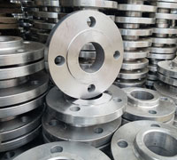
ANSI B16.5 Slip On Flange
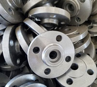
ANSI B16.5 Socket Weld Flange
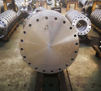
ANSI B16.5 Blind Flange
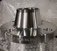
ANSI B16.5 Weld Neck Flange
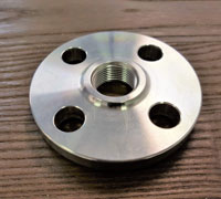
ANSI B16.5 Threaded Flange
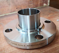
ANSI B16.5 Lap Joint Flange
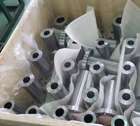
ANSI B16.5 Long Weld Neck Flanges
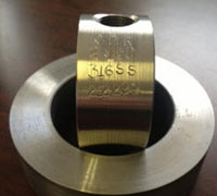
ANSI B16.5 Bleed Ring Flange
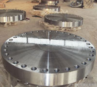
ANSI B16.5 Forged Flanges
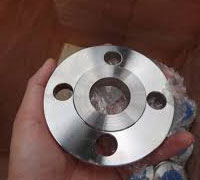
ANSI B16.5 Plate Flange
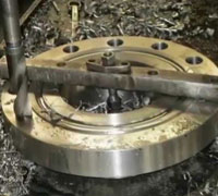
ANSI B16.5 Ring Type Joint Flange
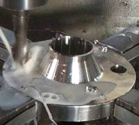
ANSI B16.5 Raised Face Flange
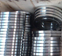
ANSI B16.5 Tongue and Groove Flange
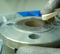
ANSI B16.5 Male and Female Flange
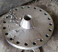
ANSI B16.5 Reducing Flange
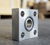
ANSI B16.5 Square Flange
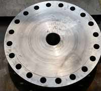
ANSI B16.5 High hub Blind Flange
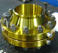
ANSI B16.36 Orifice Flanges
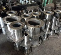
ANSI B16.5 Puddle Flange
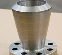
ANSI B16.5 Expander Flange
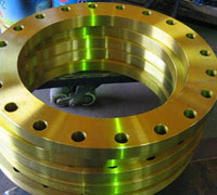
ANSI B16.5 Flat Flange
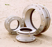
ANSI B16.5 Flange Adapter
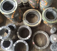
ANSI B16.5 Flange Gasket
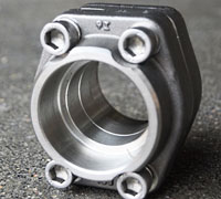
ANSI B16.5 Hydraulic Sae Flanges
